Difference between revisions of "McPherson Monochromator"
m (Add grating info) |
|||
| Line 3: | Line 3: | ||
We have in our setup the '''McPherson 302''' .2 meter scanning monochromator. Where the wavelength can be selected using the setting dial on the device or using the built-in motor. To control this built-in motor we do not have the controller but we will use an Arduino to control the motor which gives us more control over changing wavelengths within our measurement run. | We have in our setup the '''McPherson 302''' .2 meter scanning monochromator. Where the wavelength can be selected using the setting dial on the device or using the built-in motor. To control this built-in motor we do not have the controller but we will use an Arduino to control the motor which gives us more control over changing wavelengths within our measurement run. | ||
| − | ==Wavelength== | + | ==Wavelength and grating== |
| − | The limit switches define the movement limit of the motor without damaging the components: | + | We can choose the desired output wavelength by turning a grating. The grating is a 1200 G/mm concave corrected grating, Al+MgF2 coated, VUV design wavelength, master holographic. |
| + | |||
| + | The limit switches on the monochromator define the movement limit of the motor without damaging the components: | ||
Lower limit: 99723 Å below 0 | Lower limit: 99723 Å below 0 | ||
Upper limit: Å (To be added) | Upper limit: Å (To be added) | ||
| Line 43: | Line 45: | ||
*[[Media:Scan controller instruction manual.pdf|Scan controller manual]] | *[[Media:Scan controller instruction manual.pdf|Scan controller manual]] | ||
*[[Media:789A-4-Commands&example.pdf|Scan controller commands list]] | *[[Media:789A-4-Commands&example.pdf|Scan controller commands list]] | ||
| − | *[[Media: | + | *[[Media:Control a McPherson spectrometer via scan controller.pdf|Scan controller how to]] |
Revision as of 11:19, 6 October 2022
This page contains information about the McPherson Monochromator.
Basic information
We have in our setup the McPherson 302 .2 meter scanning monochromator. Where the wavelength can be selected using the setting dial on the device or using the built-in motor. To control this built-in motor we do not have the controller but we will use an Arduino to control the motor which gives us more control over changing wavelengths within our measurement run.
Wavelength and grating
We can choose the desired output wavelength by turning a grating. The grating is a 1200 G/mm concave corrected grating, Al+MgF2 coated, VUV design wavelength, master holographic.
The limit switches on the monochromator define the movement limit of the motor without damaging the components:
Lower limit: 99723 Å below 0
Upper limit: Å (To be added)
The operational range of wavelength for measurement is:
nm - nm (To be added)
Motor controls
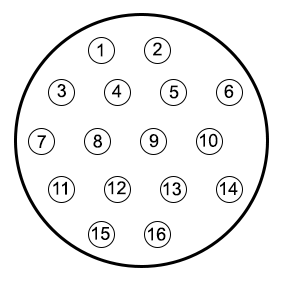
To use the built-in motor there are two connectors to consider, one directly going to the stepper motor (Parker LV231-02-10)and one going to the limit switches. The connection on the back of the monochromator connecting the limit switches is shown below. The numbers in the image correspond with numbers on the connector itself. Pin 5 and 6 are connected to one another via a blue cable, this can be used to see if you connected the connector right side up. Pin 11 and 15 is the lower wavelength switch, the front of the monochromator. Pin 13 and 16 is the higher wavelength switch, the back of the monochromator. These switches are always passing through a signal and when pressed break connection. From pins 7, 8, and 9 we do not know exactly what their purpose is. They seem to be connected to some sort of sensor determining a region.
