Difference between revisions of "ITk Endcap At Nikhef"
(add section petal test box) |
|||
| (14 intermediate revisions by the same user not shown) | |||
| Line 1: | Line 1: | ||
| + | [[File:Lower petal-wheel rim distance EC-A.pdf|thumb|Lower petal-wheel rim distance EC-A]] | ||
''[https://wiki.nikhef.nl/atlas/ITk_Endcap_Homepage Back to ITk Endcap Homepage]'' | ''[https://wiki.nikhef.nl/atlas/ITk_Endcap_Homepage Back to ITk Endcap Homepage]'' | ||
| Line 487: | Line 488: | ||
=== Wheel installation - Distances between wheel rim and lower petals === | === Wheel installation - Distances between wheel rim and lower petals === | ||
| − | For EC-A, in the [https://itkpd-test.unicorncollege.cz/componentView?code=9c7745de9896b5c95f7ccaf804e6730e wheel entries in the ITk Production database] | + | |
| + | |||
| + | [[File:Lower petal-wheel rim distance EC-A.pdf|thumb|alt=Lower petal-wheel rim distance EC-A]] | ||
| + | |||
| + | For EC-A, these are the results from the measurements of the '''distance between the wheel rim and the lower petal'''. They are also available in the [https://itkpd-test.unicorncollege.cz/componentView?code=9c7745de9896b5c95f7ccaf804e6730e wheel entries in the ITk Production database]. The purpose was to check if there's enough space for the RF box. The test was done using the measurement petal, and placing it on the lowest locking points. Each measurement was performed next to a spacer rod. Important to take into account that the locking points closer to the inner cylinder might be a bit shorter than the ones on the wheel rim (sometimes the actual height would be probably 0.5mm smaller than measured). | ||
| + | |||
| + | [[File:Lower petal-wheel rim distance EC-C.pdf|thumb|alt=]] | ||
| + | |||
| + | Due to sensor cracking, one of the potential case scenarios is that the petals will get an extra layer of material, resulting in a larger petal thickness. This could be problematic if there is not enough space between the lower petals and the wheel rims in the already built EC structures (A and C). EC-A was already measured when the RF box issue was addressed, but now EC-C as well. | ||
| + | |||
| + | [[File:EC-A with Test petal.png|left|frameless|497x497px|EC-A with Test petal]] | ||
| + | [[File:ECs deviations 7mm distance lowerPetal wheelRim.png|frameless|978x978px|Deviations from the original 7mm distance between the lower petals and the wheel rims, as a function of the position on each wheel, for both ECs|alt=|center]] | ||
=== EC geometric measurement - Stiffness === | === EC geometric measurement - Stiffness === | ||
Latest revision as of 15:44, 23 April 2024
File:Lower petal-wheel rim distance EC-A.pdf Back to ITk Endcap Homepage
The construction of the ITk Strip End-caps at Nikhef.
Author: Andrea García Alonso
Wheels
Wheel conduction after assembly
Wheel and Blade production documentation & characterisation
Wheel and Blade production documentation & characterisation
Wheel locking point measurements
Wheel locking point measurements
Wheel QA/QC
Inner ring measurements
Stiffener disk
The stiffening disks of the End-caps, made of Ultem foam with a carbon-fiber face-sheet, were produced and tested at Nikhef. The stiffening disks provide structural stiffness to the EC and act as a thermal barrier. To certify that the three manufactured stiffening disks comply with the specifications, an ATLAS internal note was written to explain the thermal deformation tests carried out at Nikhef, at the end of 2021 and the beginning of 2022. Although it is quite difficult to measure small thermal deformations on such big structures, three tests were performed: temperature changes, local temperature gradients, and global temperature gradients. The results show that the deformations in two disks are consistent with the specifications. The remaining disk is chosen as spare since it deforms above expected, although still mechanically acceptable.
You can find the ATLAS internal note called "Temperature deformation tests of the ITk strip end-cap stiffening disks produced at Nikhef" here: https://cds.cern.ch/record/2824857. In case you don't have access, please contact Andrea García Alonso.
Cooling manifolds
The ITk strip End-cap detector consists of 6 wheels that each accommodate 32 petals. The petals are cooled with a 2-phase CO2 system using cooling service modules that serve 16 petals, corresponding to half a wheel.
Status on 1st June 2023:
Disk 0 manifolds fabrication is not finished
All manifolds for disk 1 and disk 2 are fabricated, the As and Bs for disk 3 are fabricated as well. Disk 2, outlet manifolds A, B, C and D are cleaned by 31st May 2023.
Summer 2023: Pressure tests + leak tests + alcohol flushing
Every manifold is tested at a high pressure (170 bar) and a check for leaks is performed using Helium. Afterwards, every manifold is internally cleaned with alcohol to assure that no small particles could eventually block the capillarities to which the manifold will be connected.
Test reports and status available here:
| Inlet
manifold |
Produced | Preassure
tested |
Leak
tested |
Alcohol
flushed |
Ready for
installation |
Outlet
manifold |
Produced | Preassure
tested |
Leak
tested |
Alcohol
flushed |
Ready for
installation | |
|---|---|---|---|---|---|---|---|---|---|---|---|---|
| Disk 0 - A | ✓ | ✓ | ✓ | ✓ | YES | Disk 0 - A | ✓ | ✓ | ✓ | ✓ | YES | |
| Disk 0 - B | ✓ | ✓ | ✓ | ✓ | YES | Disk 0 - B | ✓ | ✓ | ✓ | ✓ | YES | |
| Disk 0 - C | ✓ | ✓ | ✓ | ✓ | YES | Disk 0 - C | ✓ | ✓ | ✓ | ✓ | YES | |
| Disk 0 - D | ✓ | ✓ | ✓ | ✓ | YES | Disk 0 - D | ✓ | ✓ | ✓ | ✓ | YES | |
| Disk 1 - A | ✓ | ✓ | ✓ | ✓ | YES | Disk 1 - A | ✓ | ✓ | ✓ | ✓ | YES | |
| Disk 1 - B | ✓ | ✓ | ✓ | ✓ | YES | Disk 1 - B | ✓ | ✓ | ✓ | ✓ | YES | |
| Disk 1 - C | ✓ | ✓ | ✓ | ✓ | YES | Disk 1 - C | ✓ | ✓ | ✓ | ✓ | YES | |
| Disk 1 - D | ✓ | ✓ | ✓ | ✓ | YES | Disk 1 - D | ✓ | ✓ | ✓ | ✓ | YES | |
| Disk 2 - A | ✓ | ✓ | ✓ | ✓ | YES | Disk 2 - A | ✓ | ✓ | ✓ | ✓ | YES | |
| Disk 2 - B | ✓ | ✓ | ✓ | ✓ | YES | Disk 2 - B | ✓ | ✓ | ✓ | ✓ | YES | |
| Disk 2 - C | ✓ | ✓ | ✓ | ✓ | YES | Disk 2 - C | ✓ | ✓ | ✓ | ✓ | YES | |
| Disk 2 - D | ✓ | ✓ | ✓ | ✓ | YES | Disk 2 - D | ✓ | ✓ | ✓ | ✓ | YES | |
| Disk 3 - A | ✓ | ✓ | ✓ | ✓ | YES | Disk 3 - A | ✓ | ✓ | ✓ | ✓ | YES | |
| Disk 3 - B | ✓ | ✓ | ✓ | ✓ | YES | Disk 3 - B | ✓ | ✓ | ✓ | ✓ | YES | |
| Disk 3 - C | ✓ | ✓ | ✓ | ✓ | YES | Disk 3 - C | ✓ | ✓ | ✓ | ✓ | YES | |
| Disk 3 - D | ✓ | ✓ | ✓ | ✓ | YES | Disk 3 - D | ✓ | ✓ | ✓ | ✓ | YES | |
| Disk 4 - A | ✓ | ✓ | ✓ | ✓ | YES | Disk 4 - A | ✓ | ✓ | ✓ | ✓ | YES | |
| Disk 4 - B | ✓ | ✓ | ✓ | ✓ | YES | Disk 4 - B | ✓ | ✓ | ✓ | ✓ | YES | |
| Disk 4 - C | ✓ | ✓ | ✓ | ✓ | YES | Disk 4 - C | ✓ | ✓ | ✓ | ✓ | YES | |
| Disk 4 - D | ✓ | ✓ | ✓ | ✓ | YES | Disk 4 - D | ✓ | ✓ | ✓ | ✓ | YES | |
| Disk 5 - A | ✓ | ✓ | ✓ | ✓ | YES | Disk 5 - A | ✓ | ✓ | ✓ | ✓ | YES | |
| Disk 5 - B | ✓ | ✓ | ✓ | ✓ | YES | Disk 5 - B | ✓ | ✓ | ✓ | ✓ | YES | |
| Disk 5 - C | ✓ | ✓ | ✓ | ✓ | YES | Disk 5 - C | ✓ | ✓ | ✓ | ✓ | YES | |
| Disk 5 - D | ✓ | ✓ | ✓ | ✓ | YES | Disk 5 - D | ✓ | ✓ | ✓ | ✓ | YES |
PP1 patch panel
Plan for QA/QC during 2024
- Tcycle a piece between +40, -35 (or reasonably low) in a dry-air or N2 bag.
- Measure ohmic R with voltmeter on ~10 places randomly.
- Measure R between all inserts and surface. R<10 Ohm, otherwise we probably need to fix. (or are all inserts grounded anyway via their bolts).
End-cap structure
Wheel installation - Positions on ECs and numbering
The produced wheels have been installed in the two end-caps as shown in the table. Wheels with Erno number 1 and 14 don't belong to any EC (spare).
| End-cap wheel
position |
Erno
number |
Dutch-shape
number |
|---|---|---|
| End-cap A - Wheel#0 | 11 | 19056-13-A7 |
| End-cap A - Wheel#1 | 2 | 19056-15-B2 |
| End-cap A - Wheel#2 | 9 | 19056-13-A3 |
| End-cap A - Wheel#3 | 13 | 19056-15-b6 |
| End-cap A - Wheel#4 | 7 | 19056-13-A2 |
| End-cap A - Wheel#5 | 12 | 19056-15-B5 |
| End-cap C - Wheel#0 | 6 | 19056-13-A1 |
| End-cap C - Wheel#1 | 4 | 19056-15-B3 |
| End-cap C - Wheel#2 | 10 | 19056-13-A4 |
| End-cap C - Wheel#3 | 5 | 19056-15-B4 |
| End-cap C - Wheel#4 | 8 | 19056-13-A6 |
| End-cap C - Wheel#5 | 3 | 19056-13-A5 |
Wheel installation - Distances between wheel rim and lower petals
File:Lower petal-wheel rim distance EC-A.pdf
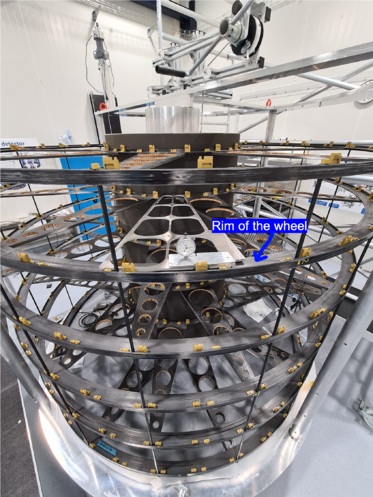
For EC-A, these are the results from the measurements of the distance between the wheel rim and the lower petal. They are also available in the wheel entries in the ITk Production database. The purpose was to check if there's enough space for the RF box. The test was done using the measurement petal, and placing it on the lowest locking points. Each measurement was performed next to a spacer rod. Important to take into account that the locking points closer to the inner cylinder might be a bit shorter than the ones on the wheel rim (sometimes the actual height would be probably 0.5mm smaller than measured).
File:Lower petal-wheel rim distance EC-C.pdf
Due to sensor cracking, one of the potential case scenarios is that the petals will get an extra layer of material, resulting in a larger petal thickness. This could be problematic if there is not enough space between the lower petals and the wheel rims in the already built EC structures (A and C). EC-A was already measured when the RF box issue was addressed, but now EC-C as well.
EC geometric measurement - Stiffness
A load of a hundred kilograms was placed inside the EC inner cylinder to mimic the operational conditions. Several 3D laser measurements indicated that the EC structures have a high stiffness leading to only 20 to 60 µm effects when loaded.
Test summary presented in the ITk week March 2024: https://indico.cern.ch/event/1353986/contributions/5865828/attachments/2822702/4929833/EC%20GEOMETRIC%20MEASUREMENT%20-%20ATLAS%20ITk%20Week%20180324.pdf
Characterization of mechanical behaviour EC structure at cold temperatures
EC structure temperature studies
Petal test box
Cleanroom at Nikhef
Miscellaneous documents
- Click here for the request regarding temporary connectors (pdf).
- ITk pictures by Jesse van Dongen
- EC mockup fb2020
