Cooling system
The cooling module for the vacuum chamber is the LN2 trap design from IdealVac. The specs for this module can be found [here].
We have the sample cooling plate from IdealVac, which has a 140ml LN2 reservoir. To fill the reservoir, asked for a quote for https://www.linde-cryo.nl/nl/producten/cryopro/dermatologische-behandeling.html - this is no longer a viable option for the setup.
First equations for LN2 required to cool
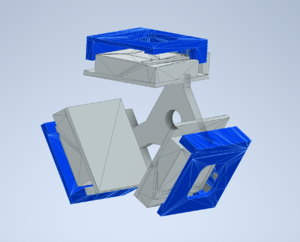
The first planned measurement is the fluorescence measurements. For these, we will use the three-faced sample holder hung from the roof of the chamber. This design is given as a thumbnail. We should also know how much LN2 is required to cool this to 173K (operating temperature). In order to calculate this, we need to know several thermal properties of the holder. This holder will be made of copper which has well-known values for heat capacity and density. The amount of heat required to achieve this from room temperature can be calculated via the equation
Q=VCp(T2-T1)
where Q is the heat energy required, V is the volume of copper used, C is the heat capacity of copper, p is the density of copper and T2-T1 is the temperature difference required. Using the standard values, C=0.389kJ/kgK and p=8940kg/m^3, the sample holder with a volume of 3.3e-4m^3 will require **115kJ** of heat energy. This heat energy will be supplied by the vaporisation of liquid nitrogen in the LN2 cooling module. This is given as 199kJ/kg with a mass as 0.8083kg per liter. Therefore, for the 140ml cooling module, the cooling system of the setup will provide **22.798kJ** per fill. This means the module should be refilled **5 times** to cool the sample holder only to 173K. Since each refill takes maximum 2 hours to evaporate (as measured under vacuum with no warm components attached to it), this is a **10-hour** procedure (of course, this will reduce when the warm elements are introduced to the system and we need not wait for all LN2 to evaporate entirely before refilling, provided we are careful of bubbling).
This same calculation for three copper cables connected to the reservoir will require **37.18kJ**, corresponding to **1-1.5** reservoir fills. In total, this sums to a maximum of **6.5** reservoir fills taking roughly **13 hours** and 1L of LN2.
Heat loss due to radiation
The Stefan-Boltzmann law describes the thermal radiation which is emitted by an object as shown in the equation
W = EsAT^4
where W is the radiation emitted, E is the emissivity of the object in question, s is the Stefan-Boltzmann constant, A is the surface of interest and T is the object's temperature. To obtain the heat loss due to radiation in a system such as our setup, the process laid out in File:Installation of a cryogenic station to perform Emission Channeling experiments at low temperature.pdf is followed. The setup in this case is one grey body (for our purposes the sample holder) surrounded by a vacuum chamber grey body. Side note: here a grey body emits radiation with different emissivities for different wavelengths - but the changes are negligible. We also assume that the radiating surfaces in question are parallel to the chamber walls - though this is not strictly the case with either of the designed sample holders. By making this assumption, we can simplify the combination of emissivities of the copper from the sample holder and the stainless steel from the chamber walls with the 'emissivity factor', F.
F = 1/Es + 1/Ec -1
where Es and Ec refer to the emissivity of the sample holder material (copper) and the chamber material (stainless steel) respectively. The emissivities taken from [Emissivities] are 0.07 for both materials, making F=27.6. The thermal flux can then be calculated via the equation
Q=-sFA(Tc^4-Ts^4)
The sample holder designed for fluorescence measurements has four surfaces of interest for these calculations: the surface facing away from the sample, the sides and top of each sample holder piece, and the thin copper base designed for thermal connection. These are easily modelled as three rectangles and a triangle as shown below.
| Figure 1: Dimensions used for surface faces. |
|---|
The total of the heat fluxes calculated for these faces (not including the bottom face which will have the frame covering it) come to Q=49.28W. For the sample holder designed for reflection measurements, this value increases to Q=101.96W due to the larger outward-facing surfaces.
In the same reference, a shield around the sample holder was calculated to reduce this by a factor of 2.
Extra considerations:
- Poor thermal connections --> File:Installation of a cryogenic station to perform Emission Channeling experiments at low temperature.pdf used capton foil to isolate the copper from the larger holder between the connection.
- Time taken for reservoir to evaporate when pieces are connected
- Heat loss to frame
- Temperature difference at each end of the copper braids
- Thermal radiation shielding --> File:Design and testing of low temperature part of an UHV – SPM microscope.pdf connected a copper braid to their shielding to cool it further. Testing this without the shield, they cooled their sample holder 30x30x45mm and 26g to 100K within 120 minutes and used 1.2l/h of LN2.
Copper cables
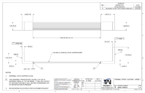
The LN2 trap will be connected to the sample holder via one copper thermal cable per sample-space. For example, the sample holder built by Casimir for reflective measurements has space for two samples and will therefore be connected to two thermal cables. These thermal cables are ordered from Technology Applications, Inc. The dimensions of which were chosen to fit within the chamber without interfering with the walls or other components, and with enough slack to twist up to 180 degrees to accommodate the movement of the sample holder. <add simulation information> The designs are given below.
| Figure 1: Thermal strap design |
|---|
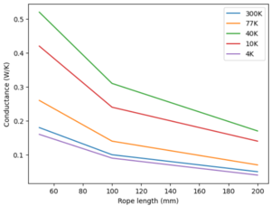
This design is based on a standard design (P6-504) from the company to reduce shipping time and increase modularity of use with both sample holders, which can be found here File:2022 CuTS® Catalog - TAI(1139).pdf. This strap is made of 9 individual copper braids with a length of 20cm and width of 2.54cm, connected to two L-shaped end pieces. Some broad thermal information is provided from the company and shown below.
| 50mm | 100mm | 200mm | |
|---|---|---|---|
| 300K | 0.18 | 0.10 | 0.05 |
| 77k | 0.26 | 0.14 | 0.07 |
| 40K | 0.52 | 0.31 | 0.17 |
| 10K | 0.42 | 0.24 | 0.14 |
| 4K | 0.16 | 0.09 | 0.04 |
To improve the conduction of the copper on braids used for cooling, File:Installation of a cryogenic station to perform Emission Channeling experiments at low temperature.pdf used gold-plated copper. This reduced the effect of the oxidation of the copper reducing the conduction.
Thermal conductivity can be used in order to determine the heat flux inside a material via the equation
Q=-k(T2-T1)/L
where Q is the heat flux, k is the conductivity, T2 and T1 are the final and initial temperatures respectively and L is the distance between the two considered points. With the copper braids ordered, the heat flux for temperatures 273K to 173K (here using the conductivity 0.05) with a transport cross-section of 1.5e-4m^2 is 125W. Once the system is cooled from room temperature, this is larger than the heat lost to radiation that the sample holder will experience.
The connection pieces of both ends of the copper braids are L-shaped to connect to the LN2 reservoir and sample holder via screws, without disrupting the thermal connection between the braid and the copper block that the connections are made from. The LN2 reservoir has pre-made screw holes and pressing the connecting piece firmly to this surface is required to reduce the thermal resistance between the two pieces. File:Design of a multi-axis cryogenic sample manipulator for soft x-ray and VUV spectroscopy.pdf found that using a key-hole shape for the connection reduced the thermal resistance by 7.6K with respect to a circular connection. This is not a huge difference but can be considered in future if our connection needs improving.
With copper braids (3mm diameter and 7.5cm length), File:Design of a multi-axis cryogenic sample manipulator for soft x-ray and VUV spectroscopy.pdf were able to cool the sample holder attached to the end of the copper braid to 84.4K within half an hour with liquid nitrogen. This was achieved after allowing the cold finger to reach liquid nitrogen temperatures. The equivalent in our setup would be to allow the reservoir to reach this temperature, which should take roughly 6 hours.
Equipment
Small dewars are widely available for LN2 handling and transportation. These come in many different sizes but based on the small 140 ml LN2 reservoir, we shouldn't need anything above 1 l to store LN2 intended for cooling the plate. Transfer out of the dewar can take place with several options, such as pouring through a spout and into a funnel or scooping small amounts out at a time. While pouring is a viable option since some dewars do come with a spout in place, scooping LN2 in a pre-determined-sized cryo dipper is a more careful and predictable way. This method can also use a simple funnel to prevent over spilling, though it should be considered also in the context of evapouration of the LN2 out of the LN2 trap, which could cause bubbling and splash on the sample chamber. Covering the chamber can prevent any accidental splashing.
From the module specs, we know that the LN2 reservoir can hold 140ml at a time. To cool this to liquid nitrogen temperatures (-196 degrees) requires 1L of LN2. From that point forwards, each 140ml of LN2 will take a maximum of 2 hours to evaporate out of the reservoir. This can of course be topped up at any convenient time to extend this time. With this in mind, we should look to get a dewar of 2L (or 3L for some extra wiggle room) to prevent needing to refill it. The dipper we use should also be capable of holding 200ml of LN2 in order to fill the reservoir in one pour, ideally with a spout to facilitate ease of movement.
Update A larger dewar maybe necessary for long cooling periods - could use one large dewar to store LN2 close by so that we don't have to run with the smaller dewar back and forth.
| Product | Price | Link |
|---|---|---|
| 2L Dewar | €216.00 | [Dewar] |
| 3L Dewar | €137.99 | [Dewar] |
| 200ml ladle | €19.95 | [Dipper] |


