Cooling system
Cooling system
   Created: 13/12/22
   Last modified: 14/12/22
https://indico.cern.ch/event/1199289/contributions/5449540/attachments/2706182/4698085/DarkNESS-TAUP2023.pdf. uses a setup similar to ours with a cryocooler
Sample holder design
Requirements:
- x-y rotational movement
- Modular wrt sample thickness (1-4mm)
- Physically fits in front of beam
- Connected to feedthrough control
- Coolable using LN2 reservoir
- High thermal conductivity for sample cooling
- Thermal isolation from rest of setup
- Thermal connections between samples
Material:
Based on some of the requirements above, the material for the sample holder should have a high thermal conductivity, low thermal expansion coefficient and be strong. The table below gives some of the options for this choice.
| Material | Thermal conductivity (W/mK) | Density (kg/m3) |
|---|---|---|
| Al-Cu alloy | 140 | 2700-2850 |
| CuCrZr alloy | 320 | 8960 |
| Al | 237 | 2700 |
| OFHC Cu | 401-409 | 8900 |
The OFHC copper was chosen for the sample holder for its thermal properties and its use in a vacuum, and was also already available in the mechanical department.
Design:
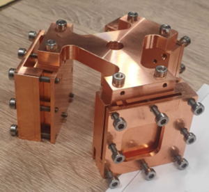
The design of the sample holder converged to its final form in Figure 1 to allow space for three samples, thermal contact between the samples via the central copper piece, and placement of the copper braids at each of the sample frames. A slot is available on each sample frame for a PT100 sensor in order to monitor the temperatures of the samples. See the wiki page [[1]] for a look at the other designs considered.
The samples are held in place by two copper pieces which make up the frame. The thermal connection between the sample and the holder is achieved by screwing the copper pieces together and using springs to tighten the connection. The sample holder will be connected to the LN2 system via copper braids. This is discussed in more detail below.
Heat equations:
The majority of the cooling power from the evaporation of LN2 will be transferred to the sample holder via conductive heat transfer. This process is dependent on the shape and material of the components, and the temperature difference to be achieved.
The amount of heat required to cool only the sample holder from room temperature to -100C can be calculated via the equation
$$Q=VCp(T2-T1)$$
where Q is the thermal energy required, V is the volume of copper used, C is the specific heat of copper, p is the density of copper and T2-T1 is the temperature difference required. Using the standard values, C=0.389kJ/kgK and p=8940kg/m^3, the sample holder with a volume of 3.3e-4m^3 will require 138kJ of heat energy. This heat energy will be supplied by the vaporisation of liquid nitrogen in the LN2 cooling module. This is given as 199kJ/kg with a mass as 0.8083kg per liter. Therefore, for the 140ml cooling module, the cooling system of the setup will provide 27.9kJ per fill. This means the module should be refilled 5 times to cool the sample holder only to 173K. Since each refill takes maximum 2 hours to evaporate (as measured under vacuum with no warm components attached to it), this is a 10-hour procedure.
The copper-copper interface is a significant source of cooling power loss. Whilst this is difficult to estimate without measuring the connection we are capable of creating, another study measured the conductance between such a connection as 40W/mK, which compares to the 125W/mK used in these calculations. This drop will be a source of loss of cooling power.
The heat conductance through an interface is described by the equation
$$\frac{dT}{(Ti-Tf)} = \exp{\frac{-hAt}{pCV}}$$
where dT is the temperature difference across the interface, (Ti-Tf) is the cooling of the object of interest and h is the heat transfer coefficient. h is dependent on the macroscopic contact of the interfaces. The better the contact, the better the cooling between the two objects. This motivates the requirement for strong connections between the pieces.
Heat loss can occur through radiative heat transfer from the walls of the sample chamber, which are at room temperature. The Stefan-Boltzmann law describes the thermal radiation which is emitted by an object as shown in the equation
$$W = E_sAT^4$$
where W is the radiation emitted, E is the emissivity of the object in question, s is the Stefan-Boltzmann constant, A is the surface of interest and T is the object's temperature. To obtain the heat loss due to radiation in a system such as our setup, the setup is one grey body (for our purposes the sample holder) surrounded by a vacuum chamber grey body.
Here a grey body emits radiation with different emissivities for different wavelengths - but the changes are negligible. We also assume that the radiating surfaces in question are parallel to the chamber walls - though this is not strictly the case with either of the designed sample holders. By making this assumption, we can simplify the combination of emissivities of the copper from the sample holder and the aluminium from the chamber walls with the 'emissivity factor', F.
$$\frac{1}{F} = \frac{1}{E_s} + \frac{1}{E_c} -1$$
where E$\_s$ and E$\_c$ refer to the emissivity of the sample holder material (copper) and the chamber material (aluminium) respectively. The emissivities are taken as 0.07 for both materials, making F=0.036. The thermal flux can then be calculated via the equation
$$Q=-sFA(T_c^4-T_s^4)$$
The sample holder designed for fluorescence measurements has four surfaces of interest for these calculations: the surface facing away from the sample, the sides and bottom of each sample holder piece, and the thin copper base designed for thermal connection. These are easily modelled as three rectangles and a triangle as shown below.
The total of the heat fluxes calculated for these faces (not including the top face which will have the frame covering it) come to Q=4.52mW. For the sample holder designed for reflection measurements, this value increases to Q=0.133W due to the larger outward-facing surfaces. An important note to keep in mind is that this model does not account for the sample. This will reduce the copper facing the walls but will introduce it's own values depending on the material.
Copper braids
Requirements:
- Thermally connect sample holder to LN2 reservoir
- Allow movement of the sample holder (without applying too much torque)
- Long enough to connect when LN2 reservoir is moved
- End piece attachment to sample holder pieces
- Thermal properties
Properties of braids
Braids thermally connect two objects whilst allowing relative movement between the objects. They consist of thin wires twisted into braids which are pressed to end pieces in a solderless process to reduce outgassing. Braids are available in copper or aluminium, depending on the mechanical motions which are required in the setup. Copper is widely preferred due to its thermal conductivity but is heavier than aluminium. The VULCAN setup requires only 120 degree rotational motion so copper is chosen for the braids.
Points considered when designing connecting braids
Using copper braids to connect the cooling apparatus to the copper sample holder introduces some new considerations. One expected loss of cooling power is at the interfaces between different components. The copper braids should have a good thermal connection with the sample holder. This has been achieved in different manners in other experiments (keyhole connections/conducting intermediate materials etc.) but in the VULCAN setup, the connections will be made with screw/spring pairs. The end pieces will slot between the sample frames and the central connecting copper pieces to maximize surface area connections. The effectiveness of this connection is difficult to predict since it is dependent on the installation of the components.
The connection of the braids to the end pieces can be achieved in several different ways. These include soldering (which introduces higher outgassing to the vacuum), mechanical cold-pressing (which can trap air between the components), vacuum pressing (to eliminate the trapped air) and electron beam welding (which has been attempted but only produces a notable effect at temperatures lower than 10K). Whilst the different methods have their challenges, the mechanical cold-pressing was chosen since it is cheaper but doesn't introduce the outgassing that a soldered connection does.
The solderless connection of the braids to the end pieces is achieved with mechanical cold-pressing. This is undertaken in an environment at room temperature and atmospheric pressure which can lead to small amounts of trapped air between the braid pieces and the copper blocks. This has been investigated in more detail in other experiments, but is not easily resolved and is not expected to be a major component in loss of cooling power in this setup.
The thermal conductivity of the straps can be improved with a few techniques. One such technique is subjecting the straps to an annealing procedure to improve the thermal conductivity. This is only expected to improve the conductance significantly in the context of temperature ranges around O(K). Another effect occurs when the braids are exposed to oxygen for extended periods of time or during handling of the braids in which a copper-oxide layer can form. This reduces the amount of electronic conduction available and leaves conduction via phonons only. This effect has been spotted in contact between two flat copper pieces, and even in the pressing of the braids to the end pieces. This effect can be avoided by plating the braids with gold. This reduction of electronic conduction is temperature dependent but only presents a significant issue at very low temperatures (sub-10K), so is not expected to have a significant impact on this setup.
If an upgrade to the system in future requires more isolation of the movement of the holder from the straps, the copper braids are available with the braid pieces unravelled. The VULCAN setup as configured here does not require this.
Copper braids on the way:
Ordered: 3x TechApp CuTS copper braids, 99.98% OFHC copper, 9x20cm braids, modified end sizes
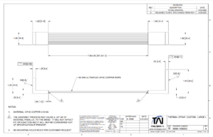
The LN2 trap will be connected to the sample holder via one copper thermal cable per sample-space. These thermal cables are ordered from Technology Applications, Inc., the dimensions of which were chosen to fit within the chamber without interfering with the walls or other components, and with enough slack to twist up to 180 degrees to accommodate the movement of the sample holder. The designs are shown in Figure 3.
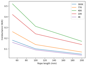
This design is based on a standard design (P6-504) from the company to reduce shipping time and increase modularity of use with both sample holders, which can be found File:2022 CuTS® Catalog - TAI(1139).pdf. This strap is made of 9 individual copper braids with a length of 20cm and width of 2.54cm, connected to two L-shaped end pieces. Some broad thermal information is provided from the company and shown below.
| Temperature | 50mm | 100mm | 200mm |
|---|---|---|---|
| 300K | 0.18 | 0.10 | 0.05 |
| 77k | 0.26 | 0.14 | 0.07 |
| 40K | 0.52 | 0.31 | 0.17 |
| 10K | 0.42 | 0.24 | 0.14 |
| 4K | 0.16 | 0.09 | 0.04 |
Cables produced by the same company were tested for use in SuperCDMS-SNOLAB at temperatures below 4.5K. This study determined the conductivity of braids of 150mm length can be improved at low temperatures by a factor of 2 by annealing the connection pieces, and attempted to electron-beam weld the connection pieces to improve the electronic conductance. This was carried out successfully but needs improvement before it can produce a useful result. However, a similar brazing technique may be considered for the connection of the cables to the LN2 reservoir. Since we will always need at least two cables for cooling, these can be allowed as constant fixtures in the chamber. This may introduce a temperature difference in the three-sided sample holder as one would be connected only by screws, but connecting these three sample frames with the central piece of copper can help to balance the temperature between the samples.
Another study detailed the cleaning procedure using deionised water, detergents and isopropanol which was undertaken on the copper braids that were made in-house for Sirius. After this cleaning procedure, the copper braids didn't affect the level of vacuum which could be reached, down to 10^-10mbar. For now, we will use isopropanol for the cleaning of the copper braids but this can be optimised in future.
Heat equations:
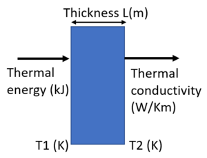
Thermal conductivity can be used in order to determine the heat flux inside a material via the equation
$$Q=\frac{-k(T2-T1)}{L}$$
where Q is the heat flux, k is the conductivity, T2 and T1 are the final and initial temperatures respectively and L is the distance between the two considered points, as shown in Figure 5. With the copper braids ordered, the heat flux for temperatures 273K to 173K (here using the conductivity 0.05) with a transport cross-section of 1.5e-4m^2 is 125W.
The connection pieces of both ends of the copper braids are L-shaped to connect to the LN2 reservoir and sample holder via screws, without disrupting the thermal connection between the braid and the copper block that the connections are made from. The LN2 reservoir has pre-made screw holes and pressing the connecting piece firmly to this surface is required to reduce the thermal resistance between the two pieces. Using a key-hole shape for the connection in previous studies reduced the thermal resistance by 7.6K with respect to a circular connection. This is not a huge difference but can be considered in future if our connection needs improving.
With copper braids (3mm diameter and 7.5cm length), others were able to cool the sample holder attached to the end of the copper braid to 84.4K within half an hour with liquid nitrogen. This was achieved after allowing the cold finger to reach liquid nitrogen temperatures. The equivalent in our setup would be to allow the reservoir to reach this temperature, which should take roughly 6 hours.
Following the conductive heat transfer calculations in the section above, this same calculation for the three copper cables connected to the reservoir will require another 20kJ, corresponding to 1 reservoir fill. In total, this sums to a maximum of 6 reservoir fills to cool the copper braids and the sample holder, taking roughly 12 hours and 1L of LN2.
The calculation to determine the radiative heat loss from between the copper braids and the chamber walls can be repeated from the section above and undertaken with the copper braids which have a surface area of 0.0087m^2. This gives the heat loss due to radiation Q=0.61mW per cable, taking the total heat loss to radiation for the fluorescence sample holder and the copper braids together to Q=6.03mW.
COMSOL calculations
Design of the sample holder
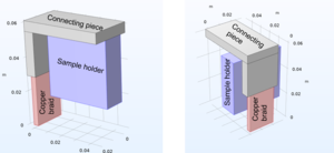
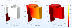
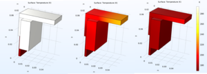
When designing the new sample holder for fluorescence measurements, two designs were considered. One design was a hollow hexagonal shape with three sample slots. The cooling braids in this configuration would connect across the top of the sample frames and hang through the center of the holder. The second design was a triangular design with three sample slots, connected by a central piece of copper. The cooling braids in this second configuration would connect also across the top of the sample frame and hang down the side of each sample frame. Examples of these design connections are shown in Figure 6.
For both designs, two copper braid end piece designs were considered. The first is the standard connector shape: an 'L'-shaped connector with both sides made of 1x1x0.6" copper rectangles (machined from just one block to avoid poor thermal connections). This was in consideration because the standard shapes are a cheaper option which would have a faster delivery time.
The 'L'-shaped design was also considered with one side of the 'L' connector slightly longer (1x1.66x0.6"). This would connect in the same configuration to the sample holder, but the extension provides more surface area in contact with the sample holder to improve the thermal connection. In all investigated designs, the copper braid connecting piece overhangs the sample holder (the amount that it overhangs is dependent on the design chosen, the connection choice and the width of the sample in the holder).
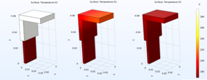
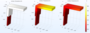
The cooling process of these braids were studied in COMSOL, using simplified geometries to increase the calculation time. The directions that the cooling gradient moved was studied along the copper cable connectors first and is shown in Figure 7.
The calculations that COMSOL evaluates can be carried out with many options. For these studies, all cooling occurs through conductive heat transfer along the braid (one end of which is held at LN2 temperature) to the connector and sample holder (which begin at room temperature). The interfaces between the copper components are assumed to be perfectly thermally connected, but this part of the cooling setup is expected to lose up to 90% of the cooling power and is highly dependent on the thermal connections possible. The study is also carried out in a perfect vacuum environment, and for now ignores radiative heat transfer between the copper components and the chamber walls.
The heat flux is calculated here via the equation
$$Q=\rho C_p \frac{\delta T}{\delta t} + \Delta \cdot \overline{q}$$
where Q is the heat flux, $\rho$ is the density of copper, $C_p$ is the specific heat of copper, T is the temperature, t is the time taken, $\overline{q}$ is the conductive heat flux which is proportional to the temperature gradient, $\overline{q}=-k\Delta T$.
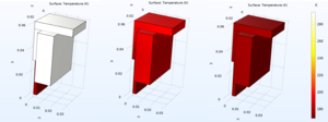
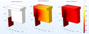
The study of cooling movement through the components was repeated with the mass of one of the sample frame included. The results are shown in Figure 8.
These studies, while simplistic, indicate that it is important to achieve a stable temperature before taking measurements to avoid a temperature gradient across the sample (and therefore different conditions for the measurements to take).
After combining these studies with mechanical and physical constraints in the chamber, the triangular sample holder was selected. This is able to physically fit in the region in front of the beam, with enough room to include a SiPM holder for fluorescence measurements. The configuration of the long copper braid end piece with this sample holder allows the most surface area contact between the copper components, and is not too much more expensive than the standard shape.
Future calculations
COMSOL can be a temperamental software since calculation times can very quickly become very large, and versions of the software which are compatible with other program (such as CAD) are not automatically included in the licenses. Problems with opening the software can often occur when the computer updates or the license provider disconnects.
Future calculations which would be good to know for the behaviour of the cooling in the system include simulated 'poor' thermal contact between different components or thin conducting materials bridging this gap for various contact pressure or conductance values. These would influence the cooling time and efficiency of the configurations. It would also be helpful to know the effect of radiative heat transfer between the components and the chamber walls in this situation to determine how much cooling power is lost in this mechanism. Another source of loss of cooling is expected between the sample holder and it's connection to the chamber. For this purpose, PTFE has been used in order to thermally isolate the holder from the chamber as much as possible, but there is still expected to be a loss here.
LN2 handling system
Amount of required LN2
The calculations in the sections above indicate that 840ml of LN2 are required to cool the sample holder + copper braids to operating temperature. In addition to this, another 6mW are required to maintain this temperature. Together, this comes to a little below one liter of LN2, depending on how long the measurement procedure will take.
After the LN2 has all evaporated and no more is poured into the LN2 reservoir, we assume that the main source of heat is the radiative heat flow from the chamber walls to the copper components. Thus, we can determine the time it would take for these components to heat back to room temperature via the equation
$$t=pVcT \frac{dT}{Q}$$
This equation indicates that it will take 7 hours for the sample holder and copper braids to heat back to room temperature. This is easily counteracted by LN2 consumption which can supply up to 3.875W per second. Thought should be given to whether a heating control (such as coiled electrical wire) should be considered to keep temperature ranges steady during measurement taking.
Components
While the calculations in this report only provide estimates for this LN2 consumption and will have to be measured when the system is set up, plans can be made for the LN2 handling system components.
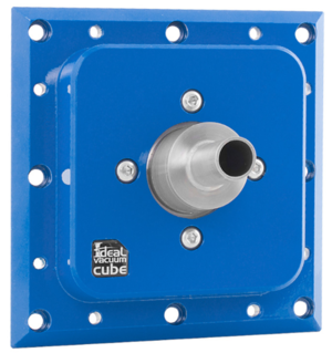
There are several options available for cooling samples down to cryogenic temperatures. Whilst some can be immediately discarded for cooling samples before moving them into a chamber for example, there are several options that have been used in vacuum chamber setups. These include He refrigerators, continuous-flow cryostats, pulse tubes and liquid gas cooling. The latter is chosen for this setup because it is a cheaper and simpler option than some of the others described, and a dedicated cooling module (Figure 9) is available from IdealVac for the modular setup.
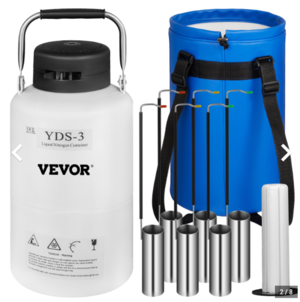
The remaining choices for the components needed are fairly straight forward. A dewar is needed which can hold more than 1L of LN2. Since some of the measurements planned are a few hours long and therefore will require more LN2 to maintain the cold temperatures, a 3L dewar provides more legroom. The dewar chosen is shown in Figure 7 and is an aluminium alloy material with a transport bag. To transfer the LN2 from the dewar to the LN2 module, a few options were considered. A LN2 gun or some pressure-based transport system was suggested which would have been ideal so there was less chance of spillage, however none were found that were the right system for what we had in mind. A dewar which had a small spout was found which would allow pouring straight from the dewar to the module. This wasn't available in the 3L size. A ladle + funnel system was chosen since the distance to move the LN2 will be short and only a little is required at a time. Care should be taken not to spill the LN2 on the sample chamber, and to avoid the evaporating LN2 from bubbling inside the module and spitting. If needed, a gas-escape 'straw' can be included to reduce this effect.
Other upgrades/future studies
Shielding
In these types of setups, cooling power is expected to be lost through radiative heat transfer between the cooled components and the chamber walls at room temperature. One method to reduce the heat lost this way is to implement a thermal shield between these parts. Thermal shields consist of layers of materials which slow down the heat transfer between either side. The more layers, the slower the heat transfer.
This has been used in previous studies to reduce the loss by up to a factor of two. This value is dependent on the emissivity and conductive resistance between the layers of the shield used. There are several materials which can be used to make these radiation shields, most notably aluminium since it has a high conductance.
Implementing this technology can also help to reduce the condensation on cold surfaces, such as the sample, by introducing increased areas for this condensation to form on and encouraging less build up on the sample surface. This has an effectiveness based on the temperature that it will be held at and the surface area it introduces to the system. There is also equipment which is designed specifically for this use: LN2 traps.
Hydrocarbons in vacuum systems are introduced via the pumps, outgassing and contaminated surfaces. When a filter or lens is used in the setup, VUV light can break the bonds in these hydrocarbons and rearrange the molecules which are deposited onto the surface of these components. This is not an immediate concern since no filters or lenses are used, but if they are to be introduced at a later date, photochemical deposition can cause an intensity loss ~20%. This can be reduced down to the O(1)% level by introduction of a cold trap. If such a trap is desired, this can be achieved by moving the heat electrically via a Peltier element, or by cooling an area of foil (for example) around the path of the light to encourage the build up on this surface. Also helpful in future could be copper particulate traps.
Test cooling apparatus
Once the equipment arrives, the cooling efficiency of the system should be tested. This involves implementing the temprature sensors in sensible locations to test the rate of change of temperature for various parts of the setup (sample holder/copper braid ends/test sample etc.). This should be investigated under different conditions such as vacuum, amount of copper pieces attached, tightining or loosening the screw/spring combinations etc. Also to be tested is the time taken for the LN2 to evaporate from the cooling module with and without the copper pieces attached. The extent to which we can stabilise the temperature should also be checked. If this proves to not be possible with just the LN2 addition control, temperature regulating mechanisms should be checked.
Temperature control
Some methods to control the temprerature of the sample holder include using heating coils (wires wrapped around the copper which can be heated) or a heating resistor. These have been used previously to control the temperature to within 1K, depending on the implementation. Other studies used a sample holder which was able to detach from the cooling braids when the temperature fell too low - our setup does not currently have this ability since the braids will be screwed tightly to the holder. Temperature should be monitored as close to the samples as possible (the current sample holder design allows for the placement of the PT100s between the samples and the copper holder).
Wire/cable placement
The copper braids will be connected to the sample holder in three locations in this setup. These are somewhat close together, and care should be taken that the braids do not touch the chamber walls to prevent them from cooling the chamber walls, or each other so there's no risk of freezing and cracking. This was taken into account when choosing the design for these braids, but should be checked and optimised inside the chamber when they are available.
Thermal connections made
The thermal connections between all cooling elements in this setup are currently set to be achieved through the use of screws and springs to mechanically press the components together. Since the interfaces between components are expected to cause a loss of cooling power, this method may be optimised once components are available. Previous studies have used keyhole shapes to slot components together or intermediate gels or foils to aid in the macroscopic connections.
COMSOL calculations
This is noted in the COMSOL calculations section.
Interface temperature increase
The thermal connections between the connection pieces and the LN2 reservoir and sample holder can be a significant cause of heat loss. Pressing these into place firmly (to the point of minor deformation of the copper) greatly reduces the thermal resistance and other studies determined that at these points a temperature drop of 1K is possible after proper pressing. However, this may still need improving in our setup. Small foils with high thermal conduction can be placed between connections and pressed into place to reduce gaps and improve the heat flow through these points. Some studies used annealed indium foil for this purpose. It is also possible to find gels which can fulfill this purpose, but given the vacuum environment which we need to create, these outgas and reduce our ability to get to low enough vacuums.
For use with reflectance sample holder
The cooling system is also planned to be used with the reflectance sample holder and setup. This should be possible since the designs for the copper braids were chosen to be modular with respect to the sample holder used.
