Difference between revisions of "SiPMs"
| Line 50: | Line 50: | ||
|[[File:PCB refrence.PNG|PCB refrence.PNG]] | |[[File:PCB refrence.PNG|PCB refrence.PNG]] | ||
|} | |} | ||
| + | |||
| + | ===SiPM readout installation=== | ||
| + | |||
| + | While the SiPMs will be operating inside the vacuum chamber, all electronics will be housed outside the chamber. This requires that the bias and signal be transmitted through a vacuum feedthrough on the side of the chamber. The readout system prepared for this case is detailed below. | ||
| + | |||
| + | In order for the SiPMs to operate, they require a bias voltage of 56 V (with the first signals visible at 53 V and no exceeding 57 V). We use a dedicated power supply to provide this bias. The bias supply and the signal cables must be fed through a feedthrough on the side of the chamber into the vacuum. The schematic created for the cabling through the three feedthroughs in place is shown below. This also includes the cables for the temperature readouts. This feedthrough has been creating a significant level of noise on the readouts. To reduce some of this noise, a Ferrite ring has been wound (twice) around the connecting cable <details>. The connections of the cables to the inside of the feedthrough are currently individual cases and are very difficult to manually connect – a better solution to this will be considered. | ||
| + | |||
| + | [[File:Feedthrough schematic.png|thumb|Feedthrough schematic.]] | ||
| + | |||
| + | The bias supply is passed through a circuit board which also includes the amplifier <details> and high-pass filter. The amplifier in the board also requires a power supply which is connected separately, but both are joined to a common ground, along with the circuit board and the vacuum chamber itself. The high-pass filter is used to eliminate any noise which has a smaller frequency than the combination of resistor and capacitor will allow via the equation: | ||
| + | |||
| + | [[File:High-pass filter equation.png|center|frame]] | ||
| + | |||
| + | This frequency is set by a <value> Ohm resistor and a <value> capacitor, resulting in a frequency-pass value of 2 MHz which corresponds to the expected dark noise rate of the VUV SiPMs used. reduces a large portion of the noise on the base signals. This resistor can be changed out to control the filter, but this will also affect the gain on the readout signals. A larger resistor value will increase the gain on the system and vice versa. This should be balanced according to the signals achievable when all light leaks have been eliminated. | ||
Revision as of 07:49, 31 August 2022
XAMS SiPMs
Hamamatsu S13370-3050CN sensitive in the VUV region
Data sheet VUV SiPMs S13370 series
Data sheet (sensor specific)
XAMS filter electronics design shown below. This will be used to connect the sensor to a bias source as well as the amplifier to read out the signal.
Sensor troubleshooting
How to connect the sensor
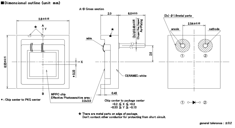
The SiPM has a cathode and an anode as can be seen in the schematic drawing below, the drawing also shows how the SiPM is oriented as a diode. A SiPM needs to be reversed biased, which means the voltage at the cathode is higher than at the anode. This way there is no current flowing until the electric field is so high the SiPM brakes down, the brake down voltages of the used SiPMs is also shown below. Sensor 1804 was already marked as defect, but we still used it to test our electronics just to be sure it worked without breaking a new sensor. This sensor first gave signals which made it seem like it was still working, but after switching around electronics we were not able to get a signal. We therefore decided to check all the used sensors if they are broken. We decided upon the convention of using the wire with an extra bit of kapton for the red/cathode connection and the black/anode connection without any extra kapton.
|
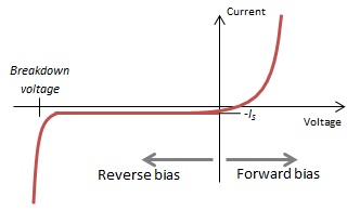
Wanting to check if a sensor is working correct we asked Martin van Beuzekom for the R & D lab to help us and helped us with a method to determine if a sensor is broken. First we wanted to check if the anode and cathode were indeed oriented as was depicted on the schematics. To check this we need to characterize the voltage vs. current. The characteristic graph of how this would look like could be found below. So what we do to check, is connect the SiPM with what we think is the cathode to the positive of the voltage source and the anode to the negative. We then apply a very low (around 0.1 [V]) voltage on the SiPM and increase it in steps of 0.1 [V]. If the diode is broken the current will increase linearly, and when the voltage applied is negative it will be again linear. This implies the diode is just an open connection and thus broken. If when the positive voltage is applied we see an exponential growth in the current we know it is connected in forward biasing mode. We then flip the current and we then expect the current to increase only in the region of the breakdown voltage.
So sensor 1804 gave the linear characteristic, confirming to us it is broken and cannot be used to check our electronics.
Cable impedance and noise
This information about will be discussed in more detail on the page Impedance on cables.
Notes
RAW notes Martin on SiPMs and impedances
Grappa muon electronics
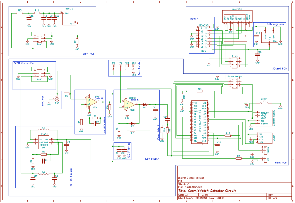
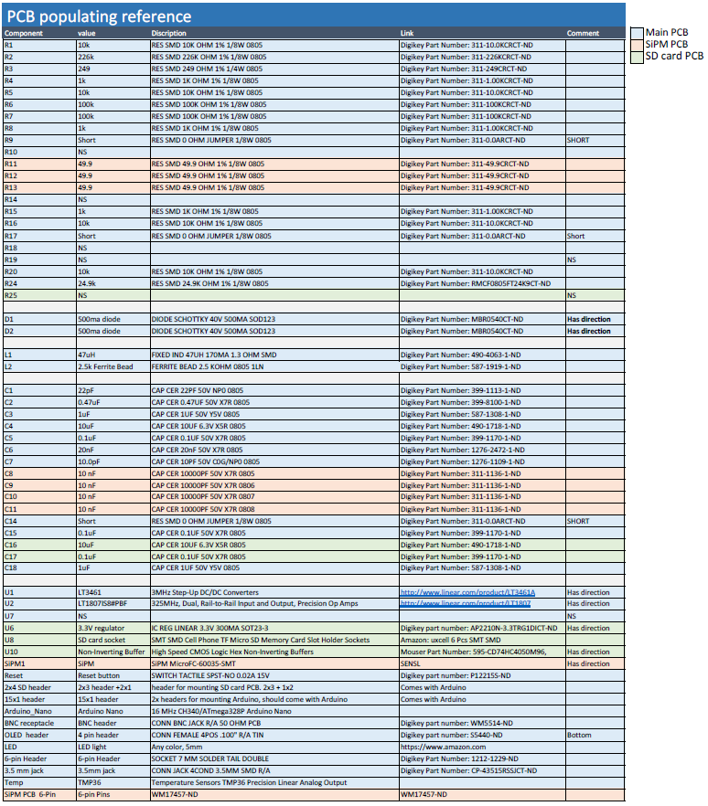
We were able to borrow a SiPM readout board from the muon project. The schematics of the electronics and refrence table can be found below.
|
|
SiPM readout installation
While the SiPMs will be operating inside the vacuum chamber, all electronics will be housed outside the chamber. This requires that the bias and signal be transmitted through a vacuum feedthrough on the side of the chamber. The readout system prepared for this case is detailed below.
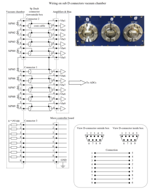
In order for the SiPMs to operate, they require a bias voltage of 56 V (with the first signals visible at 53 V and no exceeding 57 V). We use a dedicated power supply to provide this bias. The bias supply and the signal cables must be fed through a feedthrough on the side of the chamber into the vacuum. The schematic created for the cabling through the three feedthroughs in place is shown below. This also includes the cables for the temperature readouts. This feedthrough has been creating a significant level of noise on the readouts. To reduce some of this noise, a Ferrite ring has been wound (twice) around the connecting cable <details>. The connections of the cables to the inside of the feedthrough are currently individual cases and are very difficult to manually connect – a better solution to this will be considered.
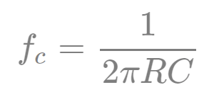
The bias supply is passed through a circuit board which also includes the amplifier <details> and high-pass filter. The amplifier in the board also requires a power supply which is connected separately, but both are joined to a common ground, along with the circuit board and the vacuum chamber itself. The high-pass filter is used to eliminate any noise which has a smaller frequency than the combination of resistor and capacitor will allow via the equation:
This frequency is set by a <value> Ohm resistor and a <value> capacitor, resulting in a frequency-pass value of 2 MHz which corresponds to the expected dark noise rate of the VUV SiPMs used. reduces a large portion of the noise on the base signals. This resistor can be changed out to control the filter, but this will also affect the gain on the readout signals. A larger resistor value will increase the gain on the system and vice versa. This should be balanced according to the signals achievable when all light leaks have been eliminated.

