Difference between revisions of "Sensor connections"
| (18 intermediate revisions by 2 users not shown) | |||
| Line 1: | Line 1: | ||
| − | This page contains the information about the connections made with the sensors trough the electrical feedthroughs | + | ==Feedthroughs== |
| + | This page contains the information about the connections made with the sensors trough the electrical feedthroughs. There are three feedthroughs as seen on the image below, the different feedthroughs will be numbered. We will also, when possible try to keep every feedthrough dedicated to one sort of sensor. The pins will be number 1 to 9 from top-left to bottom right as showed in the schematic below. | ||
| + | {| style="margin: auto;" | ||
| + | |[[File:DsubSchematic.jpg|frameless|750px|caption]] | ||
| + | | | ||
| + | |[[File:FeedthroughNumbered.jpg|frameless|750px|caption]] | ||
| + | | | ||
| + | | | ||
| + | * Feedthrough 1: Not dedicated | ||
| + | * Feedthrough 2: Temperature sensors | ||
| + | * Feedthrough 3: SiPM's | ||
| + | |} | ||
| + | |||
| + | ==Motor Control== | ||
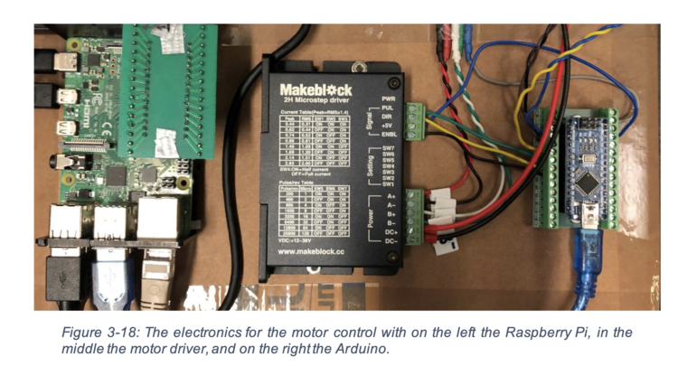
| + | With the old Arduino the connections looked as follows. | ||
| + | |||
| + | [[File:Screenshot 2023-08-01 at 13.55.27.png|750px|Connection for arduino to motor and stepper driver]] | ||
==Temperature sensor== | ==Temperature sensor== | ||
===Temperature sensor 1=== | ===Temperature sensor 1=== | ||
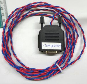
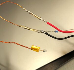
| − | The first temperature sensor will be connected using a D-sub feedthrough | + | The first temperature sensor will be connected using a D-sub feedthrough number 2. And will be connected using pin 1 (blue) and pin 6 (red). To be able to read-out the sensor a voltage of 3.3V is applied over the sensor and a 1K resistor. The voltage over the sensor is measured and conversed into a resistance, which will be used for determining the temperature. |
| − | >[[File: | + | {| |
| + | |<center>Cable outside</center> | ||
| + | [[File:Temperature Cable.jpg|frameless|caption]] | ||
| + | | | ||
| + | |[[File:TemperatureConnection.jpg|frameless|caption]] | ||
| + | | | ||
| + | |<center>Cable inside</center> | ||
| + | [[File:TemperatureSensor.jpg|frameless|caption]] | ||
| + | |} | ||
| + | |||
| + | ===Temperature sensor 2=== | ||
| + | tekst | ||
| + | |||
| + | |||
| + | ===Temperature sensor 3=== | ||
| + | tekst | ||
| + | |||
| + | ==Silicon Photomultipliers== | ||
| + | The Carlton setup uses these pins https://www.solidsealing.com/products/14/SMP-50-Ohm-Grounded-Shield-Recessed-Double-Ended-500V-CF2-75-Flange-Without-Plug/ | ||
| + | |||
| + | but it seems we can live with the standard instrumentation feedthroughs we already have. | ||
| + | |||
| + | ===SiPM 1=== | ||
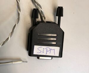
| + | The first SiPM will be connected using a D-sub feedthrough number 3. And will be connected using pin 1 (grey) and pin 6 (white). | ||
| + | {| | ||
| + | |<center>Cable outside</center> | ||
| + | [[File:SiPMConnector.jpg|frameless|caption]] | ||
| + | | | ||
| + | |[[File:TemperatureConnection.jpg|frameless|caption]] | ||
| + | | | ||
| + | |<center>Cable inside</center> | ||
| + | [[File:TemperatureInside.jpg|250px|frameless|caption]] | ||
| + | |} | ||
| + | == Impedance on cables == | ||
| + | Every cable has a certain impedance, and this impedance is the ratio between the voltage and current of a single wave propagating along the line. When the impedance of cables and electronics is mismatched these waves can reflect creating more waves. This results in noise, is is therefore very important to make sure all cables connected have the same impedance. The cable in the vacuum close to the SiPM sets the baseline, which in our case is 50[Ω]. And thus every cable we add to the system has to have an impedance of 50[Ω] | ||
| − | == | + | ===Notes=== |
| − | + | [[Media:Notes Martin on cables.pdf|RAW notes Martin on SiPMs and impedances]] | |
Latest revision as of 11:59, 1 August 2023
Feedthroughs
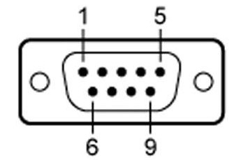
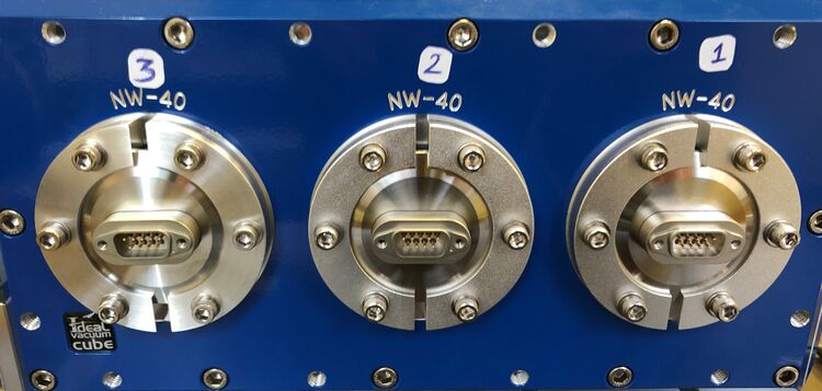
This page contains the information about the connections made with the sensors trough the electrical feedthroughs. There are three feedthroughs as seen on the image below, the different feedthroughs will be numbered. We will also, when possible try to keep every feedthrough dedicated to one sort of sensor. The pins will be number 1 to 9 from top-left to bottom right as showed in the schematic below.
|
|
|
Motor Control
With the old Arduino the connections looked as follows.
Temperature sensor
Temperature sensor 1
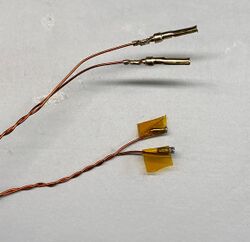
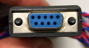
The first temperature sensor will be connected using a D-sub feedthrough number 2. And will be connected using pin 1 (blue) and pin 6 (red). To be able to read-out the sensor a voltage of 3.3V is applied over the sensor and a 1K resistor. The voltage over the sensor is measured and conversed into a resistance, which will be used for determining the temperature.
|
Temperature sensor 2
tekst
Temperature sensor 3
tekst
Silicon Photomultipliers
The Carlton setup uses these pins https://www.solidsealing.com/products/14/SMP-50-Ohm-Grounded-Shield-Recessed-Double-Ended-500V-CF2-75-Flange-Without-Plug/
but it seems we can live with the standard instrumentation feedthroughs we already have.
SiPM 1
The first SiPM will be connected using a D-sub feedthrough number 3. And will be connected using pin 1 (grey) and pin 6 (white).

|
Impedance on cables
Every cable has a certain impedance, and this impedance is the ratio between the voltage and current of a single wave propagating along the line. When the impedance of cables and electronics is mismatched these waves can reflect creating more waves. This results in noise, is is therefore very important to make sure all cables connected have the same impedance. The cable in the vacuum close to the SiPM sets the baseline, which in our case is 50[Ω]. And thus every cable we add to the system has to have an impedance of 50[Ω]
