Difference between revisions of "FELIX instructions for Petals"
(format) |
(→Performing a Strobe Delay Scan: - ABCs IDs issue) |
||
| (17 intermediate revisions by the same user not shown) | |||
| Line 1: | Line 1: | ||
[[DAQ systems|''Back to DAQ systems'']] | [[DAQ systems|''Back to DAQ systems'']] | ||
| − | |||
| + | Note on repositories: The YARR repo needs to be (at least) on commit 2169a65b63c94e5eda9789908b62eab325dffb3d: https://gitlab.cern.ch/desy-atlas/itk/YARR/-/blob/2169a65b63c94e5eda9789908b62eab325dffb3d | ||
| + | [[File:20240516 114002.jpg|left|thumb|530x530px|PPB-R5-petal setup at Nikhef May 2024]] | ||
How to configure a petal (main instructions taken from DESY repo https://gitlab.cern.ch/desy-atlas/itk/petal-testing): | How to configure a petal (main instructions taken from DESY repo https://gitlab.cern.ch/desy-atlas/itk/petal-testing): | ||
| Line 31: | Line 32: | ||
Click on ''Read Cfg'', then you can ''Quit.'' | Click on ''Read Cfg'', then you can ''Quit.'' | ||
| − | * Push the lpGBT config to the petal chipset : <code>'''fice -G0 -I71 configs/lpgbt/lpgbt_PT_M_LH_V1_Pri_hex.cnf'''</code> | + | * Push the lpGBT config to the petal chipset: <code>'''fice -G0 -I71 configs/lpgbt/lpgbt_PT_M_LH_V1_Pri_hex.cnf'''</code> |
If this command takes a long time, it's because of the LV PSU, probably due to have been providing power for a long time. | If this command takes a long time, it's because of the LV PSU, probably due to have been providing power for a long time. | ||
| Line 40: | Line 41: | ||
| + | In a second remote terminal session ''cd'' into the ''petal-testing'' directory and then execute the following commands: | ||
| + | * Configure the YARR dependencies: <code>'''source dependencies/setupYARR.sh'''</code> | ||
| + | |||
| + | * Activate the AMAC: <code>'''write_amac_ppb 9 1 0 0'''</code> | ||
| + | |||
| + | This will increase the current in the LV PSU, typically from 165 mA to 405 mA, at least these are the numbers at Nikhef with the R5 Vancouver petal. It's important to check this change in the consumption, since it confirms there's communication with the chips. | ||
| + | |||
| + | In the terminal running Felixcore, a new line will appear saying "Opening DEVICE 0 for the To-FLX thread". | ||
| + | |||
| + | * Confirm there's communication with the HCCs via a register dump scan: <code>'''python3 scantools/run_YARR.py -c scanSetup_regDump.json --infile-dir scantools/configs_PPB_Vancouver_R5'''</code> execute it '''twice'''!! (once per HCC) | ||
| + | |||
| + | After the 2nd time, there shouldn't be lines like "There were no results for chip Stave_PPB_hcc1". | ||
| + | |||
| + | Also: after the first regsiter dump scan, the current in the LV PSU will increase from 405 mA to 514 mA, and Felixcore will show the lines "Subscription from endpoint 127.0.0.1:37645 for elink 0" and "Subscription from endpoint 127.0.0.1:39225 for elink 2". After the second regsiter dump scan the current will increase from 514 mA to 605 mA, and Felixcore will show the lines "Subscription from endpoint 127.0.0.1:42045 for elink 0" and "Subscription from endpoint 127.0.0.1:46479 for elink 2". | ||
| + | === Performing a Trim Scan === | ||
| + | The ''trimScanWithRange'' optimizes the trim and threshold values of the chip at the same time, thus this scan takes a while (around 45'): <code>'''python3 scantools/run_YARR.py -c scanSetup_trim.json --infile-dir scantools/configs_PPB_Vancouver_R5'''</code> | ||
| + | This scan uses the following json files: | ||
| − | In a | + | - to configure which scans to use: ''/petal-testing/scantools/configs_PPB_Vancouver_R5/scanSetup_trim.json'' |
| + | |||
| + | - to define the actual scan (scan config): ''/YARR/configs/scans/star/std_trimScanWithRange.json'' | ||
| + | |||
| + | So if you want to use a different scan from YARR, you need to change it in ''/scantools''. | ||
| + | |||
| + | In /''data'', you should now find a subdirectory called ''XXXXXX_std_trimScanWithRange'', with ''TrimDacVsThreshold'' plots looking like the following ones (for HCCs 0 and 1): | ||
| + | |||
| + | <gallery> | ||
| + | File:HCC0 chip0 trim.png|HCC0 Chip 0 trim scan. Run 102 | ||
| + | File:HCC1 trim chip0.png|HCC1 Chip 0 trim scan. Run 102 | ||
| + | File:HCC0 trim scan.pdf|HCC0 rest of chips trim scans. Run 102 | ||
| + | File:HCC1 trim scan.pdf|HCC1 rest of chips trim scans. Run 102 | ||
| + | </gallery>Check that for both HCCs, the ''StarTrimDACResult'' JSON files exist. | ||
| − | |||
| − | + | === Performing a Strobe Delay Scan === | |
| + | Before performing the scan, enter the results of the previous trim scan in the configuration of the strobe delay (SD) scan: | ||
| − | + | 1) Edit the ''scantools/configs_PPB_Vancouver_R5/scanSetup_SD.json'' and enter the previous run number in the field ''"input_trim_from_run": "/XXXXXX"''. | |
| − | + | 2) Run the scan using the command <code>python3 scantools/run_YARR.py -c scanSetup_SD.json --infile-dir scantools/configs_PPB_Vancouver_R5</code> | |
| − | + | NOTE: In my case, the run_YARR.py file had some issues for the strobe delay scan: lines 121 and 156 contained "for iABC in range(10):" trying to access 10 ABCs, when there's only 9. I modified them to "for iABC in range(9):" | |
| − | + | In the output directory, the ''OccVsStrobeDelayVsChan'' plots should look somewhat like this: | |
Latest revision as of 17:19, 30 May 2024
Note on repositories: The YARR repo needs to be (at least) on commit 2169a65b63c94e5eda9789908b62eab325dffb3d: https://gitlab.cern.ch/desy-atlas/itk/YARR/-/blob/2169a65b63c94e5eda9789908b62eab325dffb3d

How to configure a petal (main instructions taken from DESY repo https://gitlab.cern.ch/desy-atlas/itk/petal-testing):
cd into the petal-testing directory and then execute the following commands:
- Setup the FELIX dependencies:
source dependencies/setupFELIX.sh
- Initialize the FLX card:
flx-init
It's normal if it says that all the channels are not aligned even if at least one actually is, we don't know why, but SR1 with staves sees the same.
- Invert the polarity (for lpGBTv1):
flx-config set GBT_RXPOLARITY=0xFFFFFFFF
- Verify the status of the PODs:
flx-info POD
- Check that all connected links are aligned:
flx-info GBT
If testing the PPB R5 Vancouver Petal:
- Configure the elinks on your FELIX card:
source configs/elinks/elinks_petal_R5_640Mbs.sh
- Check your config:
elinkconfig
Click on Read Cfg, then you can Quit.
- Push the lpGBT config to the petal chipset:
fice -G0 -I71 configs/lpgbt/lpgbt_PT_M_LH_V1_Pri_hex.cnf
If this command takes a long time, it's because of the LV PSU, probably due to have been providing power for a long time.
- Verify this has worked (you should see the line "Compared 336 values, found 0 differences"):
fice -G0 -I71 -C configs/lpgbt/lpgbt_PT_M_LH_V1_Pri_hex.cnf
- Start FELIXCore and don't close this terminal:
startFelixcore
In a second remote terminal session cd into the petal-testing directory and then execute the following commands:
- Configure the YARR dependencies:
source dependencies/setupYARR.sh
- Activate the AMAC:
write_amac_ppb 9 1 0 0
This will increase the current in the LV PSU, typically from 165 mA to 405 mA, at least these are the numbers at Nikhef with the R5 Vancouver petal. It's important to check this change in the consumption, since it confirms there's communication with the chips.
In the terminal running Felixcore, a new line will appear saying "Opening DEVICE 0 for the To-FLX thread".
- Confirm there's communication with the HCCs via a register dump scan:
python3 scantools/run_YARR.py -c scanSetup_regDump.json --infile-dir scantools/configs_PPB_Vancouver_R5execute it twice!! (once per HCC)
After the 2nd time, there shouldn't be lines like "There were no results for chip Stave_PPB_hcc1".
Also: after the first regsiter dump scan, the current in the LV PSU will increase from 405 mA to 514 mA, and Felixcore will show the lines "Subscription from endpoint 127.0.0.1:37645 for elink 0" and "Subscription from endpoint 127.0.0.1:39225 for elink 2". After the second regsiter dump scan the current will increase from 514 mA to 605 mA, and Felixcore will show the lines "Subscription from endpoint 127.0.0.1:42045 for elink 0" and "Subscription from endpoint 127.0.0.1:46479 for elink 2".
Performing a Trim Scan
The trimScanWithRange optimizes the trim and threshold values of the chip at the same time, thus this scan takes a while (around 45'): python3 scantools/run_YARR.py -c scanSetup_trim.json --infile-dir scantools/configs_PPB_Vancouver_R5
This scan uses the following json files:
- to configure which scans to use: /petal-testing/scantools/configs_PPB_Vancouver_R5/scanSetup_trim.json
- to define the actual scan (scan config): /YARR/configs/scans/star/std_trimScanWithRange.json
So if you want to use a different scan from YARR, you need to change it in /scantools.
In /data, you should now find a subdirectory called XXXXXX_std_trimScanWithRange, with TrimDacVsThreshold plots looking like the following ones (for HCCs 0 and 1):
HCC0 Chip 0 trim scan. Run 102

HCC1 Chip 0 trim scan. Run 102

HCC0 rest of chips trim scans. Run 102
HCC1 rest of chips trim scans. Run 102


Check that for both HCCs, the StarTrimDACResult JSON files exist.
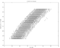
Performing a Strobe Delay Scan
Before performing the scan, enter the results of the previous trim scan in the configuration of the strobe delay (SD) scan:
1) Edit the scantools/configs_PPB_Vancouver_R5/scanSetup_SD.json and enter the previous run number in the field "input_trim_from_run": "/XXXXXX".
2) Run the scan using the command python3 scantools/run_YARR.py -c scanSetup_SD.json --infile-dir scantools/configs_PPB_Vancouver_R5
NOTE: In my case, the run_YARR.py file had some issues for the strobe delay scan: lines 121 and 156 contained "for iABC in range(10):" trying to access 10 ABCs, when there's only 9. I modified them to "for iABC in range(9):"
In the output directory, the OccVsStrobeDelayVsChan plots should look somewhat like this: