Sample holder
There are two designs for the sample holder. One design for reflection and transmission measurements by Casimir, and one for the fluorescence measurements. Both are made out of copper for cooling of the sample. Good thermal connection is achieved by pressing the sample to the copper with screws with springs. For both designs cardboard models are available (on the experiment table). There are also models of the cooling braids (with different attachment types) and a mock-up of a sensor holder.
Reflection and Transmission Sample Holder
The sample holder will be positioned off-axis from the exit slit of the monochromator. It will hold two samples. The samples can be positioned at an angle with respect to the beam in order to do reflection measurements. There is a hole at the back for transmission measurements. The sample holder is on a base that is attached to a rotary feedthrough at the bottom of the vacuum chamber. See Casimir's thesis for more information.
Fluorescence Sample Holder
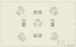
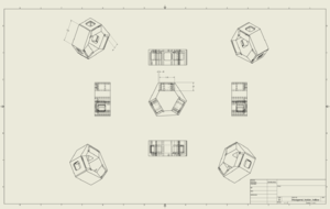
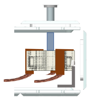
This sample holder will be positioned directly in front of the exit slit from the monochromator. So the beam will illuminate the sample straight from the front. We designed this sample holder such that it will hold three samples simultaneously (see also the images). One of the samples can be a reference, one can be a blank, and one can be the sample to measure. Both designs are still in the running, a definitive decision will be made soon. Cooling braids will be attached at three places. The sample holder will in this situation be suspended from the top of the vacuum chamber and connected to a rotary feedthrough at the top of the vacuum chamber. An impression is shown in the images. On the left you can see the cardboard model of the sample holder and how it will fit inside the vacuum chamber. When suspended from the feedthrough, it still has enough room to rotate, and a holder for the SiPMs can be placed between the sample holder and the opening to the monochromator without difficulty. It would be best if the SiPM wires are going down along the SiPM holder and then out to the side where the feedthrough is. The cooling braids will be able to come out either at the top or the bottom of the sample, and the position of the cooling plate can be adjusted to match the desired flexibility. The temperature sensor wires can then go opposite the cooling braids to the feedthroughs. In this way, the wires will not get tangled when turning the sample holder, and the copper wires will not touch any material.


