Difference between revisions of "SiPMs"
Jump to navigation
Jump to search
| Line 19: | Line 19: | ||
|- | |- | ||
|1804 | |1804 | ||
| + | | | ||
| + | | | ||
| + | |- | ||
|1805 | |1805 | ||
| + | | | ||
| + | | | ||
| + | |- | ||
|1822 | |1822 | ||
| + | | | ||
| + | | | ||
|} | |} | ||
Revision as of 09:04, 22 February 2022
Useful resources:
XAMS SiPMs
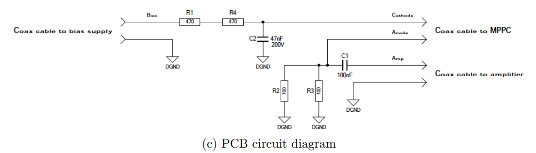
XAMS readout board design shown below.

Circuit design of signal filter boards used in XAMS lab.
Connecting the sensor to the filter
The SiPM has a cathode and an anode as can be seen in the schematic drawing below. A SiPM needs to be reversed biased, which means the voltage at the cathode is higher than at the anode. This way there is no current flowing until the electric field is so high the SiPM brakes down.

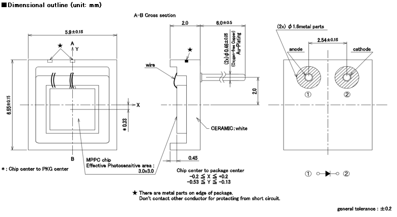
Schematic drawing of the S13370-3050CN SiPM
| Serial No. | Vop at M=2.55e6 [V] |
Id at Vop [μA] |
| 1804 | ||
| 1805 | ||
| 1822 |