Difference between revisions of "Status updates"
| Line 12: | Line 12: | ||
| S13360-6075CS || 2 || Operational | | S13360-6075CS || 2 || Operational | ||
|- | |- | ||
| − | | S13370-3050CN || | + | | S13370-3050CN || 1805 || Broken |
|- | |- | ||
| − | | S13370-3050CN || | + | | S13370-3050CN || 1810 || Broken |
|- | |- | ||
| S13370-3050CN || 1812 || Operational | | S13370-3050CN || 1812 || Operational | ||
|- | |- | ||
| − | | S13370-3050CN || | + | | S13370-3050CN || 1822 || Operational |
|- | |- | ||
| − | | S13370-3050CN || | + | | S13370-3050CN || 1823 || Broken |
|- | |- | ||
| S13370-3050CN || 1828 || Broken | | S13370-3050CN || 1828 || Broken | ||
| + | |- | ||
| + | | S13370-3050CN || 1829 || Operational | ||
|- | |- | ||
| S13370-3050CN || 1830 || Operational | | S13370-3050CN || 1830 || Operational | ||
| − | |||
| − | |||
|} | |} | ||
Revision as of 09:27, 17 November 2022
Update 15/11/22
The SiPMs were tested one by one in the sample chamber with the readout system connected to determine whether they were operational. The oscilloscope was connected and the current across the SiPM, and visible signals at the operating voltage were used to determine the status of the SiPM. This study was prompted by the observation of several SiPMs with bent pins from the polystyrene packaging. The table below indicates the status of each SiPM.
| SiPM type | SiPM number | Status |
|---|---|---|
| S13360-6075CS | 1 | Operational |
| S13360-6075CS | 2 | Operational |
| S13370-3050CN | 1805 | Broken |
| S13370-3050CN | 1810 | Broken |
| S13370-3050CN | 1812 | Operational |
| S13370-3050CN | 1822 | Operational |
| S13370-3050CN | 1823 | Broken |
| S13370-3050CN | 1828 | Broken |
| S13370-3050CN | 1829 | Operational |
| S13370-3050CN | 1830 | Operational |
Update 31/10/22
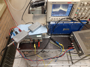
The feedback resistor on the readout board which influenced the low-pass filter was changed to reduce the noise visible in the signals. The readout board has been placed in a metal box in order to try to shield the readout from the noise in the surroundings which was previously causing some issues. This significantly reduced any noise on the signal and single-photon signals are now easily observable on the oscilloscope. After dissassembling, cleaning and reassembling the setup, the connection to the monochromator was adjusted since it seemed there was a notable difference in the height at which they were sitting. This eliminated any light source in the chamber and improved the pressure down to 3e-5mbar. The difference in height here may have been exerting some pressure on the connection which caused one side to angle and let in light/air. The Ferrite bead was also removed as this was not significantly improving the noise levels.
An amplifier board was connected to the readout board with three times 10x amplification from three OPA847 amplifiers. These are the same amplifiers which are used on the Zurich board. This takes our signals into the O(V) range which is large enough to be seen on the digitiser. These amplifiers require a power supply of $\pm$ 5V which is supplied by a separate power supply. Everything for the readout board and the amplifier board is connected to the same common ground, defined by the plug connector and accessible through a metal plate. Some wires have been taped together (or apart) to reduce the noise introduced through cable interference and copper tape has been used to ground the chamber and table parts to the common ground.
The dark count rate was estimated by eye for the SiPMs. Both were on the order of 700,000Hz which is a little lower than we expect but the measurements were not precise so we will revisit this problem if it still exists in the DAQ. When turning on the lamp with the slit closed, no extra signals are visible. When opening the slit very slightly, a jump in signals is clear, indicating the lamp is really introducing light to the sample chamber and the SiPM is really seeing it. Light responses were measured with a wavelength of 400nm.
Update 14/10/22
A period of noise-hunting determined that the most significant noise is originating from the cable connection from the Oscilloscope to the readout board. This noise disappears when the cable is held at the right angle. Hans will try and fix this source of noise.
Update: this has been changed and the noise has disappeared.
Update 6/10/22
The pre-amp noise is not coming from the power source, as previously thought. It is noise picked up from the environment. Putting the readout board in a metal casing would help to reduce this noise.
Update 5/10/22
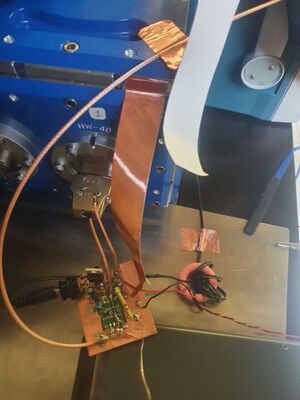
Hans from the electronics department has built a more professional version of our small readout board. The schematic is shown on the previous page. This readout board contains several features which are summarised again here for clarity. The bias supply is implemented through this board via the red and black cables seen on the right hand side. These supply the 56V bias to the SiPM from a basic power supply which is connected to the ground. The SiPM signal is then fed through the golden cable into the feedthrough and to the SiPM. The signal is read out through this same cable and fed onto the board. The board passes this through a high-pass filter to eliminate noise with low frequencies and into the pre-amp. The high-pass filter and pre-amp both rely on the feedback resistor to set their values. This is easily modifiable by changing out the resistor. Currently, the pre-amp only multiplies the signal by a factor of 1. The pre-amp is powered through a normal mains outlet which is passed through a Ferrite bead (seen in pink) before the connection. In order to ground this supply, an extra plug is placed in the outlet used and connected to the metal sheet resting on the table. This is the common ground used for all parts of the readout. To keep this common ground, the same outlet is also used for all plugs used to power components. To reduce noise from the setup, copper tape is used to connect the chamber, board and ground plate, and the two sections of the table which were found to also be producing noise.
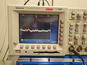
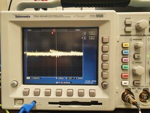
This readout system allows peaks of ~1mV to be seen on the oscilloscope (also connected to the common ground). The amplifier is still producing noise roughly 2mV in height. This noise is regular so it is possible to subtract this from the signals in analysis but we will still look at removing it manually.
This readout was connected up to the chamber. A new connector plug was built with permanent connection of the SiPM bias/signal wires to their correct feedthrough positions. This prevents finicky work inside the chamber for longer periods of time. The anode wire for the SiPM is connected to the wire marked with kapton tape and the cathode to the bare wire. After tightening the wires, this doesn't introduce any noticeable noise into the system. They were also cleaned with isopropanol before insertion.
The VUV-sensitive SiPM 1828 was connected and the chamber and closed up. In a dark environment, the noise from the pre-amp is present but SiPM signals are still clearly visible underneath this. These signals peak at ~1mV, indicating they are single-PE signals and there weren't many noticeable larger SiPM signals to indicate multiple-PE signals were present. Though there is still a small light leak, this is reduced. There is also a small vacuum leak which is expected to be in the same location. We can hence confirm that the light leak that was present before the cleaning is no longer such a problem. This was probably fixed by tightening the connections around the chamber.
The lamp fan was moved to the same outlet as the readout electronics and switched on to determine whether the noise that was present from this source was still a problem for the readout. The fan introduced no new noise so either the noise was solved through common grounding or moving the cables may have eliminated it. Switching on the lamp with the slits closed also introduced no new noise or significantly more multiple-PE signals.
The chamber was pumped down with the cables and SiPMs inside to determine their effect on the vacuum and the vacuum's effect on the signals. Minimum operating pressure of 10^-3mbar was reached without issue within 30 minutes. Wiping the cables with isopropanol is fine for now to keep a clean enough environment for the pump. The vacuum pump exacerbated the noise from the pre-amp a little when turned on. This may be due to the vibrations of the pump on the table itself which moves some wires. There are some interesting-shaped signals when the pump is still ramping up to 1500Hz, but this is not a problem for the signal readouts afterwards.
The pre-amp is currently not producing any amplification of the signal. This is adjustable through the resistor values which still need to be balanced, and an amplifier board will also be connected. This resistor is placed in a feedback position in order to control this amplification. However, the amplification currently acts on the current, which is later converted into a voltage signal. The Zurich group have sent us a spare board from their setup which utilizes a transimpedence amplifier. This works by converting the signal first into a voltage output and then amplifying it. A drawback is that it also flips the signal to a negative pulse. This should not be an issue as the digitiser ordered should be able to handle both positive and negative pulses. If it does matter, however, it is simple to flip the signal again to create positive pulses. This will be investigated in future, but for now, there is an observable single-PE signal from inside the vacuum with the lamp on and slits closed.


