Difference between revisions of "Sample holder"
| (4 intermediate revisions by the same user not shown) | |||
| Line 5: | Line 5: | ||
== Fluorescence Sample Holder == | == Fluorescence Sample Holder == | ||
| − | [[File:Sample holder central.png|thumb]] | + | |
| − | [[File:Sample holder hollow.png|thumb]] | + | {| class="wikitable" |
| + | |+ | ||
| + | |- | ||
| + | ! !! | ||
| + | |- | ||
| + | | Central design || |[[File:Sample holder central.png|thumb]] | ||
| + | |- | ||
| + | | Hollow design || [[File:Sample holder hollow.png|thumb]] | ||
| + | |} | ||
| + | |||
| + | |||
This sample holder will be positioned directly in front of the exit slit from the monochromator. So the beam will illuminate the sample straight from the front. We designed this sample holder such that it will hold three samples simultaneously (see also the images). One of the samples can be a reference, one can be a blank, and one can be the sample to measure. Both designs are still in the running, a definitive decision will be made soon. Cooling braids will be attached at three places. The sample holder will in this situation be suspended from the top of the vacuum chamber and connected to a rotary feedthrough at the top of the vacuum chamber. An impression is shown in the images. On the left you can see the cardboard model of the sample holder and how it will fit inside the vacuum chamber. When suspended from the feedthrough, it still has enough room to rotate, and a holder for the SiPMs can be placed between the sample holder and the opening to the monochromator without difficulty. It would be best if the SiPM wires are going down along the SiPM holder and then out to the side where the feedthrough is. The cooling braids will be able to come out either at the top or the bottom of the sample, and the position of the cooling plate can be adjusted to match the desired flexibility. The temperature sensor wires can then go opposite the cooling braids to the feedthroughs. In this way, the wires will not get tangled when turning the sample holder, and the copper wires will not touch any material. | This sample holder will be positioned directly in front of the exit slit from the monochromator. So the beam will illuminate the sample straight from the front. We designed this sample holder such that it will hold three samples simultaneously (see also the images). One of the samples can be a reference, one can be a blank, and one can be the sample to measure. Both designs are still in the running, a definitive decision will be made soon. Cooling braids will be attached at three places. The sample holder will in this situation be suspended from the top of the vacuum chamber and connected to a rotary feedthrough at the top of the vacuum chamber. An impression is shown in the images. On the left you can see the cardboard model of the sample holder and how it will fit inside the vacuum chamber. When suspended from the feedthrough, it still has enough room to rotate, and a holder for the SiPMs can be placed between the sample holder and the opening to the monochromator without difficulty. It would be best if the SiPM wires are going down along the SiPM holder and then out to the side where the feedthrough is. The cooling braids will be able to come out either at the top or the bottom of the sample, and the position of the cooling plate can be adjusted to match the desired flexibility. The temperature sensor wires can then go opposite the cooling braids to the feedthroughs. In this way, the wires will not get tangled when turning the sample holder, and the copper wires will not touch any material. | ||
| Line 17: | Line 27: | ||
|- | |- | ||
|[[File:Sample holder as it will be placed in the vacuum chamber.jpg|left|thumb]] | |[[File:Sample holder as it will be placed in the vacuum chamber.jpg|left|thumb]] | ||
| + | |- | ||
|[[File:Setup 3D drawing.png|thumb|A 3D impression of the sample holder inside the vacuum chamber. Cooling braids are attached to the sample holder. A SiPM holder, with SiPMs, is shown between the sample and the beam entrance.]] | |[[File:Setup 3D drawing.png|thumb|A 3D impression of the sample holder inside the vacuum chamber. Cooling braids are attached to the sample holder. A SiPM holder, with SiPMs, is shown between the sample and the beam entrance.]] | ||
|} | |} | ||
| Line 26: | Line 37: | ||
|- | |- | ||
|[[File:Vacuum chamber with sample holder for size comparison.jpg|left|thumb]] | |[[File:Vacuum chamber with sample holder for size comparison.jpg|left|thumb]] | ||
| + | |- | ||
|[[File:A model of the SiPM holder.jpg|left|thumb]] | |[[File:A model of the SiPM holder.jpg|left|thumb]] | ||
|} | |} | ||
| Line 76: | Line 88: | ||
Both side connection simulations took 24 s to reach the target temperature, whereas the back connections took only 20 s. This is explained through the slightly larger area of thermal connection which is available from the arrangement of the back connection. | Both side connection simulations took 24 s to reach the target temperature, whereas the back connections took only 20 s. This is explained through the slightly larger area of thermal connection which is available from the arrangement of the back connection. | ||
| − | The comparison between the four arrangements in terms of cooling times and heat movement is very slight. However, the back connections (which correspond to the hollow sample holder design shown above) have a better connection and therefore cool more readily. The longer connection piece does aid this cooling process but not by a significant amount and therefore if the quote does come back as significantly more expensive, it | + | The comparison between the four arrangements in terms of cooling times and heat movement is very slight. However, the back connections (which correspond to the hollow sample holder design shown above) have a better connection and therefore cool more readily. The longer connection piece does aid this cooling process but not by a significant amount and therefore if the quote does come back as significantly more expensive, it may not be strictly necessary to reach low temperatures. |
Further work will investigate poor thermal connections and possibly slowing increasing the complexity of the geometries to try to include all realistic variables in the COMSOL environment. The time taken for the sample holder to heat back up after this cooling will also be studied to get a better idea of the amount of LN2 handling needed during the running of the experiment. | Further work will investigate poor thermal connections and possibly slowing increasing the complexity of the geometries to try to include all realistic variables in the COMSOL environment. The time taken for the sample holder to heat back up after this cooling will also be studied to get a better idea of the amount of LN2 handling needed during the running of the experiment. | ||
| + | |||
| + | =Conclusions= | ||
| + | |||
| + | The central sample holder design is preferred because machining it will require less copper and be easier to machine. Attaching the cooling braids will be less finicky and reduce the chance of the braids coming into contact and freezing together. The copper braid connecting piece will not overhang as far out which provides more room for the light sensors in the vacuum chamber. The simulations show that the cooling will be slightly slower, however this may change when proper thermal connections are implemented along the vertical edges and should not significantly impact the cooling time. The copper braid designs are roughly the same price so the longer connectors would be preferable to increase thermal contact areas. Mock-up testing has shown that the sample holders have enough room in the chamber and the cooling braids allow for sufficient rotational flexibility. | ||
Latest revision as of 15:31, 2 September 2022
There are two designs for the sample holder. One design for reflection and transmission measurements by Casimir, and one for the fluorescence measurements. Both are made out of copper for cooling of the sample. Good thermal connection is achieved by pressing the sample to the copper with screws with springs. For both designs cardboard models are available (on the experiment table). There are also models of the cooling braids (with different attachment types) and a mock-up of a sensor holder.
Reflection and Transmission Sample Holder
The sample holder will be positioned off-axis from the exit slit of the monochromator. It will hold two samples. The samples can be positioned at an angle with respect to the beam in order to do reflection measurements. There is a hole at the back for transmission measurements. The sample holder is on a base that is attached to a rotary feedthrough at the bottom of the vacuum chamber. See Casimir's thesis for more information.
Fluorescence Sample Holder
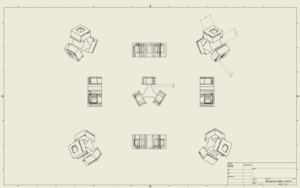
| Central design | |
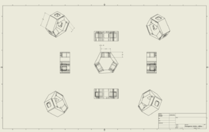
| Hollow design |
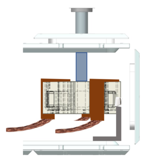
This sample holder will be positioned directly in front of the exit slit from the monochromator. So the beam will illuminate the sample straight from the front. We designed this sample holder such that it will hold three samples simultaneously (see also the images). One of the samples can be a reference, one can be a blank, and one can be the sample to measure. Both designs are still in the running, a definitive decision will be made soon. Cooling braids will be attached at three places. The sample holder will in this situation be suspended from the top of the vacuum chamber and connected to a rotary feedthrough at the top of the vacuum chamber. An impression is shown in the images. On the left you can see the cardboard model of the sample holder and how it will fit inside the vacuum chamber. When suspended from the feedthrough, it still has enough room to rotate, and a holder for the SiPMs can be placed between the sample holder and the opening to the monochromator without difficulty. It would be best if the SiPM wires are going down along the SiPM holder and then out to the side where the feedthrough is. The cooling braids will be able to come out either at the top or the bottom of the sample, and the position of the cooling plate can be adjusted to match the desired flexibility. The temperature sensor wires can then go opposite the cooling braids to the feedthroughs. In this way, the wires will not get tangled when turning the sample holder, and the copper wires will not touch any material.
Samples will be rather close to the exit slit of the monochromator, therefore the beamsize is small (around 1.5mm diameter according to earlier measurements) and the intensity is high. This is a favourable situation, since we need the beam to pass in between the SiPMs. We can control the beam size and intensity by closing or opening the exit slit. We need to investigate what a good intensity is for the experiments. We do not want to damage the materials, but we do want to see enough fluorescence.
Cooling of the sample holder
The cooling for the sample holder will be achieved by connecting the underside of the LN2 trap to the sample holder through a copper cable. This cable is available with standard 1-inch, L-shaped connecting pieces and with custom-length connecting pieces, both of which will be quoted by the end of this week. A cardboard mock-up of the cooling cable is available in the lab and the LN2 trap positioning can be adjusted for cable-position optimisation.
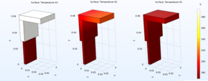
To investigate the heat flow through the cooling cable and sample holder, simulations have been run in COMSOL with both types of connecting pieces and simplified geometries. The simulation geometries are shown below.
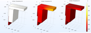
The simulations were run in timed mode to investigate how the components cool and how long it would take to reach the target temperature (170 K). Each simulation was run for 100 s and outputs were produced in intervals of 1 s. The cooling of the connection piece originates from the placement of the copper braid which is inserted into the piece with good thermal contact. For this simulation, this is assumed to be a near-perfect connection. This will be further investigated when the cables have been shipped. The short connection piece takes a total of 20 s to reach the target temperature from room temperature, whereas the long piece takes 25 s to do the same. Outputs for these simulations are shown below for both connection piece sizes at 0 s, 10 s and 20 s (left to right).
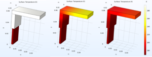
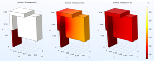
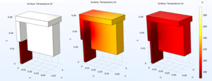
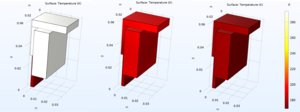
These connection pieces are then added to the sample holder which has been simplified in these geometries to a simple cube of the same proportions. The two sample holder designs under consideration will have the connection pieces attached either along the side of the holder (see the first design above) or behind the holder and through the centre of the support (see the second design above). Both of these setups have been simulated for the long and short connection pieces and are shown at 0 s, 10 s, and 20 s (left to right). These simulations also assume a very good thermal connection between both sides of the connection piece to the sample holder. This will be further investigated by simulating a situation in which the side of the connection which is attached to the braids (which cannot be screwed through) has a poor thermal connection.
| Side connection, short | |
| Side connection, Long | |
| Back connection, short | |
| Back connection, long |
Both side connection simulations took 24 s to reach the target temperature, whereas the back connections took only 20 s. This is explained through the slightly larger area of thermal connection which is available from the arrangement of the back connection.
The comparison between the four arrangements in terms of cooling times and heat movement is very slight. However, the back connections (which correspond to the hollow sample holder design shown above) have a better connection and therefore cool more readily. The longer connection piece does aid this cooling process but not by a significant amount and therefore if the quote does come back as significantly more expensive, it may not be strictly necessary to reach low temperatures.
Further work will investigate poor thermal connections and possibly slowing increasing the complexity of the geometries to try to include all realistic variables in the COMSOL environment. The time taken for the sample holder to heat back up after this cooling will also be studied to get a better idea of the amount of LN2 handling needed during the running of the experiment.
Conclusions
The central sample holder design is preferred because machining it will require less copper and be easier to machine. Attaching the cooling braids will be less finicky and reduce the chance of the braids coming into contact and freezing together. The copper braid connecting piece will not overhang as far out which provides more room for the light sensors in the vacuum chamber. The simulations show that the cooling will be slightly slower, however this may change when proper thermal connections are implemented along the vertical edges and should not significantly impact the cooling time. The copper braid designs are roughly the same price so the longer connectors would be preferable to increase thermal contact areas. Mock-up testing has shown that the sample holders have enough room in the chamber and the cooling braids allow for sufficient rotational flexibility.
