Difference between revisions of "Sensor connections"
Jump to navigation
Jump to search
| Line 1: | Line 1: | ||
| + | ==Feedthroughs== | ||
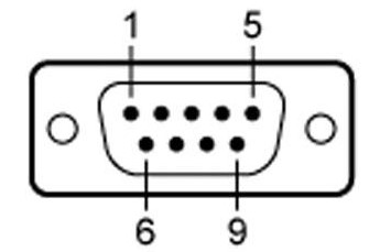
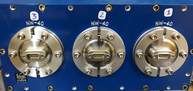
This page contains the information about the connections made with the sensors trough the electrical feedthroughs. There are three feedthroughs as seen on the image below, the different feedthroughs will be numbered. We will also, when possible try to keep every feedthrough dedicated to one sort of sensor. The pins will be number 1 to 9 from top-left to bottom right as showed in the schematic below. | This page contains the information about the connections made with the sensors trough the electrical feedthroughs. There are three feedthroughs as seen on the image below, the different feedthroughs will be numbered. We will also, when possible try to keep every feedthrough dedicated to one sort of sensor. The pins will be number 1 to 9 from top-left to bottom right as showed in the schematic below. | ||
<br><center>[[File:DsubSchematic.jpg|frameless|750px|caption]]</center> | <br><center>[[File:DsubSchematic.jpg|frameless|750px|caption]]</center> | ||
| Line 10: | Line 11: | ||
The first temperature sensor will be connected using a D-sub feedthrough number 2. And will be connected using pin 1 (blue) and pin 6 (red). | The first temperature sensor will be connected using a D-sub feedthrough number 2. And will be connected using pin 1 (blue) and pin 6 (red). | ||
{| | {| | ||
| − | |[[File:Temperature Cable.jpg|frameless|caption]] | + | |[[File:Temperature Cable.jpg|frameless|caption]] |
| | | | ||
| − | + | |[[File:TemperatureConnection.jpg|frameless|caption]] | |
|} | |} | ||
| − | == | + | ===Temperature sensor 2=== |
| − | + | tekst | |
| + | |||
| + | |||
| + | ===Temperature sensor 3=== | ||
| + | tekst | ||
| + | |||
| + | ==Silicon Photomultipliers== | ||
| + | ===SiPM 1=== | ||
| + | tekst | ||
Revision as of 13:27, 3 February 2022
Feedthroughs
This page contains the information about the connections made with the sensors trough the electrical feedthroughs. There are three feedthroughs as seen on the image below, the different feedthroughs will be numbered. We will also, when possible try to keep every feedthrough dedicated to one sort of sensor. The pins will be number 1 to 9 from top-left to bottom right as showed in the schematic below.


- Feedthrough 1: Not dedicated
- Feedthrough 2: Temperature sensors
- Feedthrough 3: SiPM's
Temperature sensor
Temperature sensor 1
The first temperature sensor will be connected using a D-sub feedthrough number 2. And will be connected using pin 1 (blue) and pin 6 (red).

|

|
Temperature sensor 2
tekst
Temperature sensor 3
tekst
Silicon Photomultipliers
SiPM 1
tekst